Announcement

Collapse
No announcement yet.

Voltage needed to drive power tubes

Collapse
X
 
  • Filter
  • Time
  • Show
Clear All
new posts

  • Voltage needed to drive power tubes

    Hello,

    I'm building an amp with a 5d8 power section and PI.

    At the moment, the amp goes triode gain stage -> gain control -> cold biased triode gain stage -> dc cathode follower (using two sides of a 12AX7; so fed by another triode gain stage) -> tone stack -> volume control -> triode-gain into paraphase -> 2x6L6 cathode biased

    I'm only getting 8W output. It should be about 25W.

    The PI is driving the 6L6s with about 60V peak to peak. Is this the cause of the low output? Should it be driving the tubes harder?


    Cathode voltage on power tubes is 24V. Plates are 363V.
    IIRC, PI has 340V through a 100K, resulting in about 160V on the plate.


    Any help would be much appreciated!

    Thanks,

    Harry


    (also, preamp sounds great - thanks to Merlin's book, which is absolutely fantastic. I am sure this is going to be the best amp I have played when I'm finished)
  • #2
    According to my data book, with the configuration you have, you should be getting about 12W. 60 volts drive signal sounds about right.
    If you need more power either reconfigure with fixed bias or raise the HT voltage. The Brimar 6L6 data sheet at Franks tube pages will have the exact voltages and loading necessary for this.

    Comment


    • #3
      Humf! Just re-checked and indeed you have it right and it should put out 24W. If the drive signal is correct then there must be a problem with output valves, output transformer, wiring in this area, power measurement method or something like that.

      Comment


      • #4
        Thanks, now I know what route to go down.

        I had to try and deduce how the OT was wired - no labelling or documentation, so it's possible that might be wrong. Time to experiment.

        Comment


        • #5


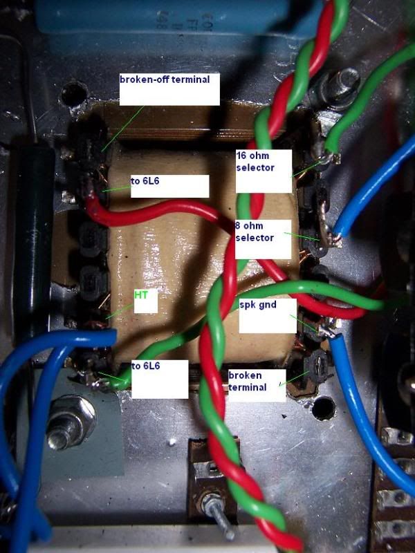
          This transformer's from a DSL401/JTM310 I think. I don't know if those terminals were snapped off on-purpose or what... Is anyone familiar with this terminal arrangement?

          clutching at straws here.
          Last edited by harry; 10-08-2009, 08:34 PM.

          Comment


          • #6
            A quick mini-lesson in tube drive.

            The linear range of tube operation as far as grid voltage is concerned is from the cathode voltage down to cutoff. That is, the grid starts drawing current if the grid goes positive with respect to the cathode, and the tube is cut off entirely when the grid voltage gets that negative.

            It is *possible* to drive the grid positive with respect to the cathode, but this takes a low impedance source drive, is very limited in how far you can drive it, and is usually heavily nonlinear.

            It is *possible* to drive the grid more negative than the cutoff point, but this is very much beating a dead horse; the tube quits conducting at cutoff and won't get any more "off" if you make it more negative.

            So the entire linear range of a tube's grid is between cathode voltage and cutoff. In an A-B output stage, this is very nearly twice the bias voltage on either tube. For a preamp tube, it's very loosely twice the cathode to grid voltage. This varies a lot more than for power stages, as the bias for a preamp tube is often more non-centered in the usable range than for power tubes.

            For the purists: Yes, I know there are situations where this is not strictly correct. It's a rule of thumb, which is what to expect things to be close to, not what is always exactly correct.

            For the normal people: sorry - I have coped with a lot of nit-picking purists.
            Amazing!! Who would ever have guessed that someone who villified the evil rich people would begin happily accepting their millions in speaking fees!

            Oh, wait! That sounds familiar, somehow.

            Comment


            • #7
              It's a Dagnall D2512 TXOP 00012

              I emailed them and they sent me a datasheet that says this:

              Customer Marshall Amplification Plc
              Description Output Transformer
              Customer Part No: TXOP-00012
              Core: 25.4mm stack of 29 laminations
              Bobbin: Single section, glass reinforced nylon thermal class "B"
              (130oC) UL94V0 core tube thickness 0.9mm typical.
              Windings: All winding wires to BSEN60317-4 (BS6811 Pt3 sect 3.1)
              Polyurethane round copper wire; Grade 1 or better
              Primary To suit 4.5K Ohms
              Secondary To suit 0-8-16 Ohms@ 35W
              Insulation 2 layers paper crepe tape between primary and secondary.
              Terminations: 2.8x0.5mm push on tags
              Finish Class "F" polyester varnish
              Assembly Interleaved construction.
              Electrical Tests: Off load performance
              2000v flash test


              which doesn't help

              Shifting it to what I imagine is the 16 ohm tap gives maybe 13 watts into an 8-ohm load. Still not right...

              I'm a bit afraid of trying that terminal that seems to be snapped off.. what could it be? Why is there a wire going to it?

              Same exists on the primary...

              Comment


              • #8
                A very useful post R.G., thank you.

                Comment


                • #9
                  Marshall® 30 W Output Transformer JTM30, JTM60, DSL401 TXOP-00012 - Etronic Shop, Amplifier & Guitar Parts

                  Found it! After hours of searching. Those terminals are cut off at the factory. So I'm fairly confident the OT is wired up correctly.

                  The PT gets a little hot... but heaters are at 6.3V....

                  Baffled.

                  Comment


                  • #10
                    ...if you have an idea of how much power (Po) you expect from the tubes (and there's sufficient plate voltage and plate current 'swings' to develop that power), and know the OT Zpp and the tubes' rated average transconductance (gm) value, here's the equation that can be backsolved to find the PI output signal (Vg.rms = half of Vgg) needed to produce that power:

                    Po = 0.9*(Zpp/4)*(gm*Vg.rms)^2

                    ...so:

                    Vg.rms ~ (1/gm)*SQRT[(4*Po)/(0.9*Zpp)]

                    ...it'll get you within ±10% of the actual design value.
                    Last edited by Old Tele man; 10-09-2009, 01:36 PM.
                    ...and the Devil said: "...yes, but it's a DRY heat!"

                    Comment


                    • #11
                      Post dc voltages throughout the amp.

                      "IIRC, PI has 340V through a 100K, resulting in about 160V on the plate." OK so what value power supply dropping resistors have you used in place of the 10K originals...I ask because your PI voltage is higher than 5D8, but your B+ is lower?

                      Output from both PI plates are comparable?

                      How have you rectified the B+?

                      Have you copied the 5D8 tone stack? If so lift the ground reference for the volume pot (post tone stack) and elminate series resistance by turning the pot full up, what happens?

                      Comment


                      • #12
                        That is a very useful-looking formula, Old Tele man, thanks.

                        Is Zpp just the primary impedance?

                        I'm still experimenting with the power supply. I've just noticed that at the moment, there's a 330ohm dropping resistor leading to 1k screen resistors that I added. The PI comes from the same point.

                        The PI is getting 368V. The screens are getting 361V. I will sort this out and add an extra dropping resistor/capacitor stage, but I don't see why it would cause any problems?

                        It's rectified with 4xUF4007s and 150uF of capacitance.

                        After the PI, each subsequent stage gets 10k/32uF filters.

                        I didn't copy the 5d8 tone stack, but I will try your suggestion and see if it makes a difference.

                        The PI plates were very much unbalanced. One side (the inverted side) clipped very very early. In the mean time I've gone to a non-self-correcting version of the paraphase, which has evened things up a bit.

                        Comment


                        • #13
                          Originally posted by harry View Post
                          Is Zpp just the primary impedance?
                          ...yes, Zpp is the stipulated OT primary plate-to-plate impedance value.

                          FYI -- the equation is just an extension of the basic: P = R*I^2, with R being replace by 0.9*(Zpp/4) and I^2 being replaced by (gm*Vg.rms)^2
                          Last edited by Old Tele man; 10-10-2009, 03:09 AM.
                          ...and the Devil said: "...yes, but it's a DRY heat!"

                          Comment


                          • #14
                            Originally posted by MWJB View Post
                            Have you copied the 5D8 tone stack? If so lift the ground reference for the volume pot (post tone stack) and elminate series resistance by turning the pot full up, what happens?
                            I just tried this; it gives about 10W. So a slight increase.

                            Comment


                            • #15
                              Originally posted by R.G. View Post
                              For the purists:

                              For the normal people: sorry - I have coped with a lot of nit-picking purists.
                              ...not a problem for me, because ALL pepper tends to look like fly-shit to me (ha,ha)!
                              ...and the Devil said: "...yes, but it's a DRY heat!"

                              Comment

                              Working...
                              X