Announcement

Collapse
No announcement yet.

Working Man's 12 blows fuse

Collapse
X
 
  • Filter
  • Time
  • Show
Clear All
new posts

  • Working Man's 12 blows fuse

    Hi guys, I'm new here, and pretty ignorant about amp repair. I really want to learn to work on these things and joined this forum specifically because the members here seem to be not only very knowledgable, but also very tolerant of noobs.

    So, anyway. Here's my first project. It's any early (probably 1994) SWR Workingman's 12 100w bass amp. It blows the fuse immediately on power up. My research has led me to believe that the most likely problem is bad output transistors. I got Fender to send me a schematic, but they sent a schematic dated 2004. I believe that by 2004 the power of this model had been bumped up to 120w. This may be why the component numbers don't seem to match.

    I believe that I've identified the output transistors as two 2SC2837's. They are square with three leads and screwed to the heat sink, right? There is a smaller, similar looking component with no markings also screwed to the heat sink, I'm not sure what that is.

    Am I on the right track here? Is the correct first step to replace these two transistors? They seem to be cheap and readily availiable.

    Here is a picture of the board.


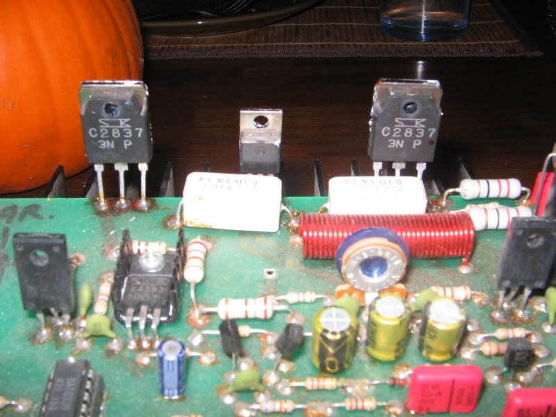
    The smaller component between the two larger ones is the one I can't identify.

    Also, I'm not sure how to attach the schematic to this post.

    Thanks, Shannon
    Last edited by tboy; 12-02-2009, 08:19 PM. Reason: fixed image tag

  • #2
    Possible fix

    Yeah, those are NPN power transistors...odd that they're the same and not complementary NPN & PNP - but I don't have the schematic to look at. They cross-reference to NTE36 (and NTE37 for the complementary PNP).

    Here's a suggestion for a quick-fix without new parts -- try cleaning all the corrosion and flux residue off the board, especially where it's shorting out those transistors. I've seen cases where that was the entire problem. Any good electronics cleaner or even common isopropyl alcohol (low water content - 90%; not the 70% stuff) and a stiff brush like an old toothbrush will do wonders for it. Clean the top and bottom, let it dry, and then try firing it up. That may eliminate the problem. If not, then it's time to start troubleshooting parts.

    Don't eliminate the possibility of problems in the power supply. Output transistors are likely culprits, but check the power-supply section just to be sure.

    Comment


    • #3
      Here's the schematic:Workingman's 12-15-2004 Power and Pre Amp Rev 1.pdf

      Comment


      • #4
        Yes, your problem might be a shorted output transistor, or it could be a shorted diode in the rectifier bridge.

        You should test the transistors to see if they are the problem before replacement. In your photo the center leg is the collector and the right leg is the emitter. Use your meter set to diode test or resistance, and see if there is a short (zero resistance) between those two legs. Test both transistors.

        The part in the middle is also a transistor, just a different case.

        You've taken the board out of the amp and have unmounted the outputs. Be sure to save the thin mica insulator sheets that isolate the transistor cases from the heatsink, as you will need to reuse them when you put this back together.

        Comment


        • #5
          I suspect those are not the original transistors. But check them for shorted.

          Try this schematic.

          The transistor in the middle would be the bias transistor Q4.
          Attached Files
          Education is what you're left with after you have forgotten what you have learned.

          Comment


          • #6
            Thanks for the responses. I followed the suggestions. I cleaned the solder points (which do appear to be original in that they look just like the rest, not like they've been re-done). I then tested the transistors according to Bill's instructions. They don't seem to read as a short. So maybe they are not burnt. They measure about 550mV in one direction and off the scale in the other.

            I then replaced the fuse and fired it up. The fuse blew.

            I think I've identified the rectifier bridge, and if I'm testing it properly, it might be the problem. When I test from the + leg to the two ~ legs, I get "off the scale" in one direction and 493 in the other direction for both. From the - to the ~, I get very similar, very low readings, in both directions. They vary from 1-4.

            As an aside, I'm having trouble reconciling what I see inside the amp to what I see on the schematic. I think I understand what the symbols mean but can't, for instance find what I think would be the rectifier bridge on the schematic. Know of any good tutorials on this? A basic power amp schematic with the parts named might be helpful?

            Thanks again, Shannon

            Comment


            • #7
              Originally posted by spsimmons View Post
              I think I've identified the rectifier bridge, and if I'm testing it properly, it might be the problem. When I test from the + leg to the two ~ legs, I get "off the scale" in one direction and 493 in the other direction for both. From the - to the ~, I get very similar, very low readings, in both directions. They vary from 1-4.
              Try testing the negative (-) side again, but hold the meter leads on for a little while. Sometimes you will be reading the charge on the filter cap, and it just takes a few seconds for the meter to discharge the cap.

              If in fact you do get low readings in both directions, then the rectifier bridge is suspect. You should remove it from the board for further testing. How are your soldering skills? What sorts of tools do you have access to?

              Comment


              • #8
                Originally posted by spsimmons View Post
                I think I understand what the symbols mean but can't, for instance find what I think would be the rectifier bridge on the schematic.
                Look on pg 2 of the 12/15/04 schematic. Coordinates 5.5, D for the rectifier bridge. It is more often drawn as four diodes, though, at least on older amps.

                RWood

                Comment


                • #9
                  So I tested the negative side again with the same result one of the ~ legs reads 1mV and the other reads 4mV, both in both directions.

                  My soldering skills are... ok, I guess. Passable, maybe? I have a cheap Greenlee DMM, an old Simpson analog MM, a cheap Radio Shack soldering iron with a questionable tip, and that might be about it for electronics specific stuff. I also have a wide range of carpentry, electrical and automotive tools.

                  I've wired from scratch a couple of electric guitars, replaced input and output jacks on amps, replaced speakers, re-soldered broken connections, but that's about it. This project is an attempt to take the next logical step in building my skills. This amp was given to me, already not working, in exchange for a simple repair job I did on a Wurlitzer piano (bad line out jack).

                  So should I pull the bridge at this point?

                  -RWood: I was actually looking at the schematic that Enzo provided when I wrote that. Looking at it again there is label at the top left that says, "A/C Terminal Bridge Rec.". So maybe the rectifier bridge is on another page?

                  Comment


                  • #10
                    Originally posted by spsimmons View Post
                    So I tested the negative side again with the same result one of the ~ legs reads 1mV and the other reads 4mV, both in both directions.

                    So should I pull the bridge at this point?
                    I would. You need to use care in removing it, as the traces on the pc board can easily be damaged. I use a small vacuum pump to remove the molten solder, making it easier to remove the parts. You might want to add one to your collection of tools.
                    Originally posted by spsimmons View Post
                    -RWood: I was actually looking at the schematic that Enzo provided when I wrote that. Looking at it again there is label at the top left that says, "A/C Terminal Bridge Rec.". So maybe the rectifier bridge is on another page?
                    The upper left connection on the power amp drawing goes to the ac connection on the bridge rectifier, which as you noted is on another page.

                    Comment


                    • #11
                      So, I finally got the rectifier bridge removed. It was a pain, but I now have a new iron, some desoldering braid, a solder sucker, and a lot more practice soldering and desoldering.

                      The - to ~ diode reads 3 in both directions. The other readings are 542, 529 and 529 in one direction and "off scale" in the other. Seems bad.
                      Last edited by spsimmons; 01-02-2010, 01:52 AM. Reason: Brain fart

                      Comment


                      • #12
                        How do I determine what new part to get. The original is marked TCI TB82. Web searches don't turn up anything.

                        Comment


                        • #13
                          Taitron Components ?

                          Comment


                          • #14
                            Yes. Thank you. I think this is correct. So would any bridge rect. that is the right shape and rated at 8A 200V work?

                            Comment


                            • #15
                              I`m inexperienced but wondered the same as you.

                              Hope someone with experience will answer.

                              Have you ever been experienced? - J. Hendrix

                              Comment

                              Working...
                              X