Announcement

Collapse
No announcement yet.

Bugs in a scratch built JTM45

Collapse
X
 
  • Filter
  • Time
  • Show
Clear All
new posts

  • Bugs in a scratch built JTM45

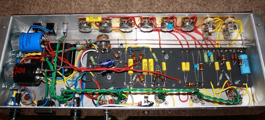
    Just got this puppy finished up tonight and I'm having trouble with loud noise [with all the levels at zero and no guitar input] and once it warms up it's popping fuses.

    Transformers: HY022798 PT, WOT45LHR OT, W022699


    Tubes: (all brand new) 3 12ax7's, 2 KT66's, 1 5AR4

    Schem followed (except bias supply) : http://www.amparchives.com/Amp%20Arc...5-readable.jpg

    Bias supply used: http://taweber.powweb.com/store/6m45_layout.jpg


    Unit makes loud noise with v3 installed. No noise without v3. Isolated problem to the position, not the tube itself. Blowing mains after a minute or so. B+ fuse is intact.

    This is all I could get before it ran me out of fuses.

    V3
    1. 399.5
    2. .049
    3. .002
    6. 398.2

    I didn't write it down but high voltage at the 5AR4 was a little over 450

    It may have been a bad quick read but it looked like a -3.xxV bias voltage ???


    Any thoughts on where/how to hunt for the bug, or any other info I can provide, until I can reload on fuses?


    Thanks, as always.
    Last edited by mort; 03-14-2013, 02:54 AM.
    ~Semi-No0b Hobbyist~

  • #2
    I like to fire a new amp up with a dim bulb tester, or current reading variac.
    It saves lots of fuses, if you have problems.
    With the dim bulb I start with the tubes out.
    If no bright lights or problems, then put tubes in.
    Then without the dim bulb, with fuses.
    Make sure you have enogh negative bias voltage.
    https://encrypted-tbn0.gstatic.com/i...iZS3o54SdhewqA
    "If Hitler invaded Hell, I would make at least a favourable reference of the Devil in the House of Commons." Winston Churchill
    Terry

    Comment


    • #3
      +1 on the bulb tester. Build that while waiting, maybe? If you have the parts lying around.

      Go over that bias supply again & again til you get more fuses. Look for mismarked resistors & check values - mistakes have been made matking them. R.G. Keen's got fuse debugging on his tube amp debugging page. Give it all a read and apply it when you get more fuses. Check the bias voltage with the power tubes out - what do you get raw with no tubes?
      Also, doesn't seem like V3 is conducting? Should be more volts on that cathode, no?
      Describe the noise, too - hum, buzz, screech, other-wordly?

      Justin
      "Wow it's red! That doesn't look like the standard Marshall red. It's more like hooker lipstick/clown nose/poodle pecker red." - Chuck H. -
      "Of course that means playing **LOUD** , best but useless solution to modern sissy snowflake players." - J.M. Fahey -
      "All I ever managed to do with that amp was... kill small rodents within a 50 yard radius of my practice building." - Tone Meister -

      Comment


      • #4
        The noise was full on hum with v3 in. BBBBBBBRRRRRRRRRRR

        This is the first occasion that I've needed a limiter, so will be putting one together asap. Might have a variac on the way too...

        Every part was checked with a meter before going in. Will check over bias circuit again for sure.
        ~Semi-No0b Hobbyist~

        Comment


        • #5
          Here is the link to the Metro Site.
          There you can download the full instruction manual for a JTM45.
          It has a power up section and lists the voltages.
          Jtm 45 kit instructions - MetroAmp Wiki
          "If Hitler invaded Hell, I would make at least a favourable reference of the Devil in the House of Commons." Winston Churchill
          Terry

          Comment


          • #6
            Attached Files
            ~Semi-No0b Hobbyist~

            Comment


            • #7
              So it only buzzes with V3 installed? Does it no longer blow fuses with V3 out?

              Yes, please do make a light bulb limiter and use it.

              Since V3 won't conduct, and you are blowing the mains fuse rather than the high voltage fuse, it leads me to think your problem might be on the heater wiring to that socket. Just a thought. Or one of the sockets.

              Does it make a difference if you leave the standby switch off?

              If none of that helps, my first option would be to power it up with no tubes at all. Verify you have 6vAC between the appropriate pins of each socket and not on the others. I'd then install the rectifier only, and fire it up, and turn the standby on. So it is ready to play except for missing the tubes. I'd verify I have B+ at pins 3 and 4 of each power tube, and improtant that we have reasonable bias voltage at pins 5. Missing bias voltage is a problem, but if the power stage had such issues, it wouldn;t care if V3 was gone.

              In the photo, far right, is that cathode bypass cap wired backwards? At the left end of the board, what looks like a bias supply has a blue cap that looks right. The black cap below it is wired the other way. If that cap is for the negative bias supply, it is backwards. If it is something else, I can;t tell from here.

              In general, the small tubes used in the preamp and phase inverter don't usually have a way to blow fuses. They are connected to the B+ through high value resistors that limit current, or even the one CF triode would have a hard time of that. Any miswired socket could do a lot of things. I have seen carefully wired nice looking work on sockets except that it was all of one pin from where it should be.

              My concern is that you have discovered that pulling V3 kills the noise, but blowing fuses is a bigger issue, and V3 may just be passing along noises that are a result of the main issue. See if it will hold a fuse (or not light the bulb) with all the tubes gone, then with ONLY the rectifier, then with just the recto and the two power tubes.
              Education is what you're left with after you have forgotten what you have learned.

              Comment


              • #8
                Regarding the "BRRRRRRRR" with V3 installed, try temporarily disconnecting the NFB loop, you may have the OT primary wires the wrong way around?

                As Enzo says, when powering up with no power tubes installed check for at least -55vdc (-60vdc if you can swing that far) at pin 5 of the power tube sockets, this way you will have the plate current set to the cool side.

                I'd remount the PI & preamp filters on the board, grounded away from the main & screen supply caps - this may alleviate some hum, but is not related to your blown fuses.

                Comment


                • #9
                  Just on a general note, regarding the bias adjuster, it's not good practice to use a (panel mount type) pot's terminals to physically mount / secure it; better to use a trimmer there.
                  Pete
                  My band:- http://www.youtube.com/user/RedwingBand

                  Comment


                  • #10
                    Just checking in from my phone, thanks for the input guys.

                    And yep, I guess I did install that cap on the right backwards. I cant hardly believe I missed that.

                    And the black cap under the bias supply is a filter coming off of the choke and first filter bank. It's layed out as shown in the weber layout.

                    Yes, the fuse still blows with v3 out, not sure about with only recto and/or power tubes or with standby off.

                    I will follow all the advice given and provide data at the first opportunity I have, probably today.
                    ~Semi-No0b Hobbyist~

                    Comment


                    • #11
                      If that cap was installed backwards, consider it toast.
                      Install a new one.

                      Comment


                      • #12
                        Ok, I was able to come home for lunch today and get a few readings. All looks normal thus far.


                        With the limiter in place, and no tubes:

                        heaters all 6.47

                        V6
                        P6 - 369.2
                        P4 - 369.5
                        P8 - 82.3
                        P2 - 84.8


                        With Rectifier in:

                        --- slight momentary burst of light on limiter when mains powered on, bigger burst of momentary light when standby engaged. Did not repeat when switched off and back on again.

                        V5
                        P3 - 494
                        P4 - 494
                        P5 - -37.67

                        V4
                        P3 - 494
                        P4 - 494
                        P5 - -37.62

                        I did go ahead and flip the cap around, will replace later. Also found an unsoldered eyelet at the diode/resister joint and soldered it. That's as far as I could get for right now. Gotta get back to work now....
                        ~Semi-No0b Hobbyist~

                        Comment


                        • #13
                          When you get time, see if you can adjust and get higher bias negantive voltage.
                          The Bias is what keeps the power tubes from run away, and pulling so much current.
                          With the tubes out and the pot at max, I would think you could get at least -50v.
                          Your -37v is low for under load conditions, I bet it will drop even lower with the tubes in, and with it off standby.
                          "If Hitler invaded Hell, I would make at least a favourable reference of the Devil in the House of Commons." Winston Churchill
                          Terry

                          Comment


                          • #14
                            V6 pins 2 & 8 - Are these AC or dc? Either way, they don't look right.

                            As Big Teee says, -37vdc on the power tube grids is most likely why your fuse is blowing, your amp is biased way hot.

                            Comment


                            • #15
                              Originally posted by big_teee View Post
                              When you get time, see if you can adjust and get higher bias negantive voltage.
                              The Bias is what keeps the power tubes from run away, and pulling so much current.
                              With the tubes out and the pot at max, I would think you could get at least -50v.
                              Your -37v is low for under load conditions, I bet it will drop even lower with the tubes in, and with it off standby.
                              Originally posted by MWJB View Post
                              V6 pins 2 & 8 - Are these AC or dc? Either way, they don't look right.

                              As Big Teee says, -37vdc on the power tube grids is most likely why your fuse is blowing, your amp is biased way hot.
                              Back home from work. Gotta love it..


                              Pins 2 & 8 of V6 are 82/84 vac each(post to ground) , a little lower with the recto in. And 4.99 vac between pins.

                              Best I can get on the bias is -38 vdc, and that's with the pot wide open. It will dial all the way down to -19.1. That's the range.

                              I have 50.0 vac out of the PT tap, -45.3 vdc after the diode, -38.9 vdc after the 10k resistor, and -37.9 after the 220k resistors, respectively.

                              How do I get the bias up?
                              Last edited by mort; 03-14-2013, 07:58 PM.
                              ~Semi-No0b Hobbyist~

                              Comment

                              Working...
                              X