Announcement

Collapse
No announcement yet.

Please help. Troubleshoot first build?!?!?

Collapse
X
 
  • Filter
  • Time
  • Show
Clear All
new posts

  • Please help. Troubleshoot first build?!?!?

    Hey guys.

    Heres what happened.

    2204 50 watt
    Triode Electronics Layout
    Hammond Transformers


    Finished the build. Plugged it in. HEard slight pop. Thought maybe it wasd the speaker since the power and standby was both flipped in. Anyway. I checked plate voltages. When I was checking this my lead slipped and arced something. Was a small arc and a small pop. I proceeded to bias amp. adjusted bias to 38MV. Tubes were still lighting up after arc. Bias was set. Thought I would plug in guitar and try it. Speaker was humming like it should so I thought it was going to work. Guitar plugged into one input I got a little volume. When it was plugged into the other input I didnt get any volume.

    Output tube voltages-
    1-
    2- 2.7 vAC I know this should be 1.15. not sure of the tolerance and my meter may be bad.)
    3- 442vDC
    4- 434 vDC
    5- -30vDC
    6- 439 vDC
    7- 2.9vAC
    8- 38 mV DC

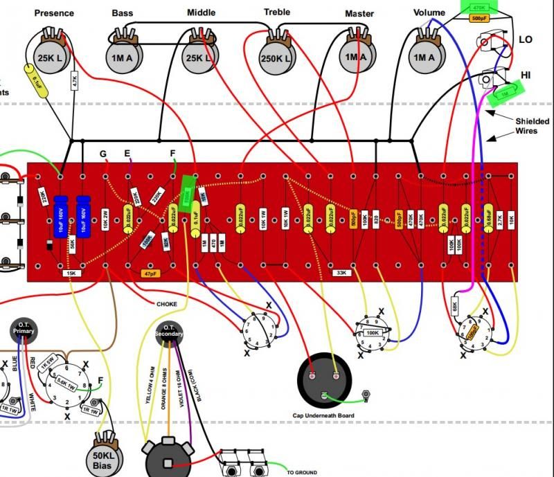
    ***************** I went through and checked all resistors. I ordered a capacitor meter also but not here yet. The image Im uploading is the layout. The THREE components with a green rectangle over them are the ones that are not reading correct. I have a 1m on the high gain thats bad. That might be why im not getting input there. I also have a 470k on the low gain that is only reading 320k. And a 100k thats bad.


    Is this a result of the arc? Or maybe were they bad? or maybe did I burn them up during soldering? Are all possibilities?
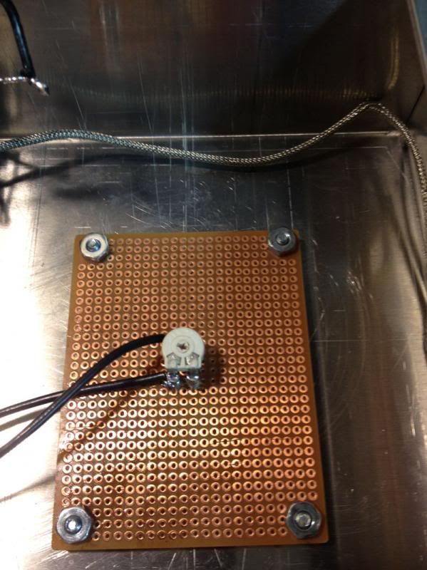
    Bias pot-
    located on opposite side of chassis.


  • #2
    ** correction.... the 100k next to the .1uf capacitor is fine

    Comment


    • #3
      Post a schematic. Buy or borrow an oscilloscope. The rest will be easy.

      Comment


      • #4
        1st preamp tube-

        pin 1- 260 vDC
        pin 2-
        pin 3-
        pin 4 and 5- 2.7 vAC
        pin 6- 220vDC
        pin 7-
        pin 8-
        pin 9 around 2.7 ACROSS BOTH pin 9 AND pin 4/5 I GET ABOUT 5.9 vAC

        2nd preamp tube-

        pin 1- 170 vDC when my lead touches this I hear a noise in the amp.
        pin 2-
        pin 3- around 2-3 vDC
        pin 4 and 5- 2.7 vAC
        pin 6- 319vDC
        pin 7-
        pin 8-
        pin 9 around 2.7 ACROSS BOTH pin 9 AND pin 4/5 I GET ABOUT 5.9 vAC

        3rd preamp tube-

        pin 1- 234 vDC when my lead touches this I hear a noise in the amp.
        pin 2-
        pin 3-
        pin 4 and 5- 2.7 vAC
        pin 6- 220 vDC
        pin 7-
        pin 8-
        pin 9 around 2.7 ACROSS BOTH pin 9 AND pin 4/5 I GET ABOUT 5.9 vAC

        Comment


        • #5
          Originally posted by hesamadman View Post
          ** correction.... the 100k next to the .1uf capacitor is fine
          As a generalization, measuring component values in circuit fraught with difficulties. Only do it if you fully understand the effect the circuit might have on the measurement.

          The most common reason for builds not working is a wiring problem so
          (1) check, check and then ask a friend to check again.
          (2) check the right components are in the right place.
          (3) Measure the DC voltages on all the preamp tubes as follows:
          pin 1 to ground,
          pin 2 to pin 3
          pin 3 to ground
          pin 6 to ground,
          pin 7 to pin 8
          pin 8 to ground
          Experience is something you get, just after you really needed it.

          Comment


          • #6
            I'll bet the input jacks are not wired correctly.
            WARNING! Musical Instrument amplifiers contain lethal voltages and can retain them even when unplugged. Refer service to qualified personnel.
            REMEMBER: Everybody knows that smokin' ain't allowed in school !

            Comment


            • #7
              guessing third preamp tube isnt getting what it needs?

              1st preamp tube-

              pin 1- 260 vDC
              pin 2- ~0
              pin 3- 2.9
              pin 4 and 5- 2.7 vAC
              pin 6- 220vDC
              pin 7- ~0
              pin 8- 2.04
              pin 9 around 2.7 ACROSS BOTH pin 9 AND pin 4/5 I GET ABOUT 5.9 vAC

              2nd preamp tube-

              pin 1- 170 vDC when my lead touches this I hear a noise in the amp.
              pin 2- ~0
              pin 3- 1.6
              pin 4 and 5- 2.7 vAC
              pin 6- 319vDC
              pin 7- 170
              pin 8- 180
              pin 9 around 2.7 ACROSS BOTH pin 9 AND pin 4/5 I GET ABOUT 5.9 vAC

              3rd preamp tube-

              pin 1- 234 vDC when my lead touches this I hear a noise in the amp.
              pin 2- 12 is this low?
              pin 3- 41
              pin 4 and 5- 2.7 vAC
              pin 6- 220 vDC
              pin 7- 13
              pin 8- 12
              pin 9 around 2.7 ACROSS BOTH pin 9 AND pin 4/5 I GET ABOUT 5.9 vAC

              Comment


              • #8
                Originally posted by hesamadman View Post
                pin 1- 170 vDC when my lead touches this I hear a noise in the amp.
                pin 1- 234 vDC when my lead touches this I hear a noise in the amp.
                You've demonstrated the basics of signal injection. the small level shift when probing the plate (pins 1 or 6 ) of your preamp tubes is amplified by the rest of the circuit and you hear a 'pop'. I'm surprised you don't get a pop (or a hummy noise) when probing pins 2 or 7. you can use this technique - with or without refining it by using a function generator or audio source - to find the places in the amp where signal SHOULD pass but DOESNT. Use the schematic for the amp, and understanding where the signal path is, you can backtrack from the output section toward the inputs, ensuring that the signal is heard before and after each component in the path. And yes, sometimes the signal is riding on high DC voltages, so protect your test gear (and your life!) with a properly-designed decoupling circuit.

                As ReddyTeddy says, post a schematic of your build, and you will get some great help debugging your amp.
                If it still won't get loud enough, it's probably broken. - Steve Conner
                If the thing works, stop fixing it. - Enzo
                We need more chaos in music, in art... I'm here to make it. - Justin Thomas
                MANY things in human experience can be easily differentiated, yet *impossible* to express as a measurement. - Juan Fahey

                Comment


                • #9
                  Originally posted by hesamadman View Post
                  pin 4 and 5- 2.7 vAC
                  pin 9 around 2.7 ACROSS BOTH pin 9 AND pin 4/5 I GET ABOUT 5.9 vAC
                  For the heaters, it is not usually beneficial to measure their voltages with respect to ground. Verifying that you have 6.3vac (plus/minus a few 1/10 of a volt) from pin 9 to pins 4 and 5 (tied together) then you've checked the heaters out OK. So 5.9vac is in the ballpark.

                  Note that this is a generalized "first pass" check, some problems may require you to investigate further.

                  Also some of your readings give a number without ac or dc. Be clear about this when posting. And be aware of polarity on the dc readings. I would expect pins 3 and 8 of V1 to be a few volts NEGATIVE. If pin 3 is 2.09vdc positive with respect to ground, that would be a very bad thing.
                  If it still won't get loud enough, it's probably broken. - Steve Conner
                  If the thing works, stop fixing it. - Enzo
                  We need more chaos in music, in art... I'm here to make it. - Justin Thomas
                  MANY things in human experience can be easily differentiated, yet *impossible* to express as a measurement. - Juan Fahey

                  Comment


                  • #10
                    Click image for larger version

Name:	voltages.jpg
Views:	1
Size:	111.7 KB
ID:	829856
                    Originally posted by eschertron View Post
                    For the heaters, it is not usually beneficial to measure their voltages with respect to ground. Verifying that you have 6.3vac (plus/minus a few 1/10 of a volt) from pin 9 to pins 4 and 5 (tied together) then you've checked the heaters out OK. So 5.9vac is in the ballpark.

                    Note that this is a generalized "first pass" check, some problems may require you to investigate further.

                    Also some of your readings give a number without ac or dc. Be clear about this when posting. And be aware of polarity on the dc readings. I would expect pins 3 and 8 of V1 to be a few volts NEGATIVE. If pin 3 is 2.09vdc positive with respect to ground, that would be a very bad thing.
                    This is a similar circuit. It only mentions one negative voltage and it is in the output section. Do i still need negative voltages in the pre? And as far as AC or DC...the only AC im getting is from heaters and the rest is DC. Is this correct?

                    Comment


                    • #11
                      Originally posted by hesamadman View Post
                      [ATTACH=CONFIG]24558[/ATTACH]

                      This is a similar circuit. It only mentions one negative voltage and it is in the output section. Do i still need negative voltages in the pre? And as far as AC or DC...the only AC im getting is from heaters and the rest is DC. Is this correct?
                      Yes of course - brain fart on my part. Pin 3 of a preamp tube (the cathode) is pulled a few volts positive by the action of the tube, and so makes pin 2 (the grid) a few volts negative in relation to pin 3 (see nickb's comments about measuring).

                      Your build will most likely be close to the chart provided. Don't be concerned at this point with small deviations. Values that are severely out of whack should direct your attention to verifying part values and wiring in attached components.

                      As you troubleshoot with finer detail, you will want to see AC signals 'riding on' the DC in the circuit; so both AC and DC measurements, if your meter allows selecting for each, will come in handy at some point.
                      If it still won't get loud enough, it's probably broken. - Steve Conner
                      If the thing works, stop fixing it. - Enzo
                      We need more chaos in music, in art... I'm here to make it. - Justin Thomas
                      MANY things in human experience can be easily differentiated, yet *impossible* to express as a measurement. - Juan Fahey

                      Comment


                      • #12
                        Originally posted by hesamadman View Post
                        guessing third preamp tube isnt getting what it needs?

                        3rd preamp tube-

                        pin 1- 234 vDC when my lead touches this I hear a noise in the amp.
                        pin 2- 12 is this low?
                        pin 3- 41
                        pin 4 and 5- 2.7 vAC
                        pin 6- 220 vDC
                        pin 7- 13
                        pin 8- 12
                        pin 9 around 2.7 ACROSS BOTH pin 9 AND pin 4/5 I GET ABOUT 5.9 vAC

                        Pin 8 is wrong
                        (1) check your measurement
                        (2) measure the voltage between pins 2 and 3, and pins 7 and 8. NOT pin 2 to ground and pin 7 to ground - doing so will give you incorrect readings.

                        As eshertron says, you discovered the crude signal injection test. You should also have pops when you touch the pins 1,2,6 and 7 of V1 assuming volume is turned up so that narrows it down a bit. Did you do steps 'check the wiring' and 'component placement'? I would concentrate on volume control/tone stack correctness.
                        Experience is something you get, just after you really needed it.

                        Comment


                        • #13
                          it looks as if my pre amp tube #3 is pretty far off. I should have around 40 vdc on 2,7, and 8. DO you have any idea why I dont?

                          Comment


                          • #14
                            I dont get anything between 2 and 3 or 7 and 8

                            Comment


                            • #15
                              Originally posted by hesamadman View Post
                              it looks as if my pre amp tube #3 is pretty far off. I should have around 40 vdc on 2,7, and 8. DO you have any idea why I dont?
                              There are a lot of components that set up that phase inverter circuit. Verify the values of all of them, check for bad solder joints, and with the power off and the tubes pulled you can take some continuity readings across various parts of that assembly. If you post a schematic with part numbers (the one I pulled up did not have components numbered, and so is just about useless for a discussion like this) it will become easy to discuss the specific values and voltages in your amp.

                              To eliminate 1 easy fix, swap tube 2 and 3 and verify that there is no change in the readings that you get.
                              If it still won't get loud enough, it's probably broken. - Steve Conner
                              If the thing works, stop fixing it. - Enzo
                              We need more chaos in music, in art... I'm here to make it. - Justin Thomas
                              MANY things in human experience can be easily differentiated, yet *impossible* to express as a measurement. - Juan Fahey

                              Comment

                              Working...
                              X