Announcement

Collapse
No announcement yet.

Amp bias indicator add-on (moved from the "microprocessor bias" thread

Collapse
X
 
  • Filter
  • Time
  • Show
Clear All
new posts

  • Amp bias indicator add-on (moved from the "microprocessor bias" thread

    This was really out of place in the thread it arose in, which was about a microprocessor setup to bias a tube amp automagically. While I've designed and built such a setup, it was really not worth the investment in time to do IMHO. A setup which let one dial in bias according to some lighted indicators (I used blue=too cold, red=too hot, and green=just right) seems to work really well, really fast, and can be done on the fly, between sets in a dark bar (for instance... ).

    I have designed much of this up, and have been tinkering with the implementation. And that quick summary gets us up to here.

    I ran into a pricing snag (as opposed to a technical challenge) when I looked at the parts that go into this thing. I'd like the benefit of the older and wiser heads on this one.

    My vision for this is a single small PCB that has on it one bias pot per tube, and one R/G/B LED per tube, with circuitry on the board that looks at the voltage across a cathode resistor per tube. The bias pot tweaks bias per tube, and the circuitry announces to you whether you're properly adjusted or not. There's more to it, but that's the basics.

    To me, having the LED in close proximity to the adjuster pot for bias makes sense. Stick a screwdriver into a pot, turn it till you get a stable green, done; go to the next tube. Your eyes are looking at something near the adjustment.

    And here's the sticky point. I had fatuously assumed that I could use a small trimmer for the bias. When I calculated "typical" values for the dissipation of the trimmer pot, I came up with about half a watt on the Fenders I used for examples. I would not use less than 1W rating for a critical (bias is CRITICAL, IMHO) application for half a watt actual power.

    I went to our friend Mouser for prices and package sizes for 1W trimmers, and that produced the issue. 1W trimmers come mostly in the long-rectangle trimmer style, start at about $5.00 and go up from there. It looks to me like the trimmer pots themselves could be expensive, and be an unforeseen driver of the design.

    Hence some questions to the pros:
    1. Would you agree with a many-turn screwdriver adjustable trimmer for a bias pot, based on human factors? Does it need to be single turn? Or multi?
    2. What's the smallest power rating you'd use for a 10K bias adjuster pot in an amp? I did my usual heavily-derated design, and the real power is probably under 1/4W, but it makes me uneasy for a bias application.
    3. One could argue that fast, accurate biasing is *worth* $5.00 a tube; what do you think?
    4. I was focusing on a small add-on board that could be done by a DIYer and put into their amp, hence the parts are deliberately small and close together, including the bias pots and indicators. Comments?
    Amazing!! Who would ever have guessed that someone who villified the evil rich people would begin happily accepting their millions in speaking fees!

    Oh, wait! That sounds familiar, somehow.

  • #2
    I dunno about older or wiser, but my thoughts. I looked at DigiKey, and pots run about $5/watt, single turn doesn't really save you much. Although I think that the biggest thing multi-turn gets you is grace in the region of interest. If you can pad either end, so that 270 degrees gets you from 5% to 70% of max dissipation, single turn is likely to be fine. You could use a single $5 pot on rough bias, and a smaller pot per tube. Or you could use a higher resistance, lower wattage pot and an emitter follower. (FJV992/KSA992) run about 20 cents in 10's, is rated for 120v and has gobs of gain.
    The prince and the count always insist on tubes being healthy before they're broken

    Comment


    • #3
      For me, a multi-turn sort of undoes the whole simplicity of the bias by lights method. It would have to at least be set up so that clockwise = hotter bias, as it would be a pain to go a whole turn or more just to find out you're going the "wrong" direction . But that's assuming clockwise=hotter is intuitive?
      Originally posted by Enzo
      I have a sign in my shop that says, "Never think up reasons not to check something."


      Comment


      • #4
        That's exactly the discussion I wanted to provoke. I did use single turn for the ones I did, and they were very easy to use. The board allocates resistor spaces for padding the ends already, so that's probably OK.

        What about size, ease, nearness of the blinky lights, etc?
        Amazing!! Who would ever have guessed that someone who villified the evil rich people would begin happily accepting their millions in speaking fees!

        Oh, wait! That sounds familiar, somehow.

        Comment


        • #5
          I've always used 15mm trimpots per tube in my amps without any problems whatsoever. In some instances I used even the 10mm version again per tube:

          PT15

          PT10

          In most production amps you can see one such trimpot for all tubes.
          If you consider this an issue maybe paralleling the trimpot with resistors will get you the 1W rating.
          IMHO multiturn trimpot is not necessary.

          I don't know how you came up with the 0.5W rating but in one of my 2xEL34 amps I measure 0.7mA current draw across the common bias supply resistor. The configuration is 1N4007 - cap - 15k resistor - cap - two 50k trimpots in parallel.
          Last edited by GainFreak; 12-09-2013, 11:06 AM.

          Comment


          • #6
            The 1W rating was a conservative, perhaps overly conservative value.

            Fender uses a 10K pot for its bias settings, simply strung across the bias supply. The raw bias voltage in most tube amps is in the 50V range, and allowing for different amps, it might be as much as 75V. 75V across 10K is 0.5625W.

            Granted, 6L6s and EL34s tend to have actual bias voltages in the -30 to -45V range, so the actual bias voltage probably won't be 75V for most amps. And using resistors to narrow the adjustment range lowers dissipation further. But I can foresee someone deciding to leave off the end resistors and use this to bias something that needs -60V bias. Hence the worry about dissipation. And given that bias should be very reliable, overdesigning the bias pots seemed to make sense.

            The bias circuit also has a pull-down resistor from wiper to full negative, so if the wiper opens, bias is not lost.

            But I think I'm going for single turn.

            Good! Thanks, guys.

            More comments?
            Amazing!! Who would ever have guessed that someone who villified the evil rich people would begin happily accepting their millions in speaking fees!

            Oh, wait! That sounds familiar, somehow.

            Comment


            • #7
              Originally posted by R.G. View Post
              More comments?
              Is it going to be just RGB, or will you also spit out a 7 segment reading in mA? Who decides what green is? If you're selling this as an add on, you need to remember that your market has a nerdy bent, even if they're conflicted about their luddite/nerd balance. They might want to know that they're at 23mA.
              The prince and the count always insist on tubes being healthy before they're broken

              Comment


              • #8
                I was a little sneaky about that. There are three adjuster pots that are not involved with the tubes. These set the following three parameters:
                - the target current; this is the place where the lights go from blue to red, and in the middle, there is a "variation parameter" in the code for how wide the light is green for. Initial setup involves some amp-nerdiness to do, as you set up one tube to the current you want (it's also calculable if you want) and mess with the target current reference pot till you get green. After that, you can adjust the other tubes (and this one again!) to the newly-set target current. The green range is 6.3 milli-diddles of the bias pot wide.
                - the overload current; this is the current where the controller says "hey, Cap'n, she can'nae gie ana moorrre!"; Again, settable by measure or calculation.
                - the overload TIME reference. This pot sets how long the overload current has to be on before the controller asserts +[warp core breach imminent] signal for someone smarter to deal with.

                And I have no plan to ever sell these. It's just for the good of humanity.
                Amazing!! Who would ever have guessed that someone who villified the evil rich people would begin happily accepting their millions in speaking fees!

                Oh, wait! That sounds familiar, somehow.

                Comment


                • #9
                  For parameters that take loctite purple, as opposed to all out fiddly user interface, if there's a micro involved, I would set those parameters via serial interface, and store them in eeprom. Get rid of single use pots wherever possible.
                  The prince and the count always insist on tubes being healthy before they're broken

                  Comment


                  • #10
                    You say "bias is critical" but I am not sure what you mean. It is critical the bias be there, but in my mind it is not critical in the sense of " it must be exactly 38.0946ma per tube" or some such.

                    And I point that out because the "precision" of a 10-turn pot is just silly in my view, the bias does not need that. A single turn twiddle pot works just fine.

                    As to running the whole bias voltage across the trimmer so it dissipates half a watt, well...

                    I don't recall which Fender amp we drew the example from, but when I suggest ways to make bias adjustable on some amp, and the solution is to make a 47k resistor variable, I also suggest they not install a 47k pot, but rather a 25k pot and a 22k resistor in series or even a 10k pot and a 33k or 39k resistor in series. The full range of voltage adjustment is not needed usually, so now instead of a large voltage across a pot, we have a much smaller voltage across a pot.

                    ALternatively, instead of looking for a hefty pot, could be not use the trimmer to control a transistor current? Thus the trimmer can be puny, the transistor is the part that dissipates.
                    Education is what you're left with after you have forgotten what you have learned.

                    Comment


                    • #11
                      Enzo etc.
                      I do use 10 turn pots - not for the precision in idle current setpoint, but for simple reliabilty. Yes the pots are more expensive but they are far better built too and so less prone to failure. Addressing bias pot failure with a "safety" resistor from wiper to full -ve bias supply is a good idea but it still leaves you with a faulty board which will require a fix.
                      To limit the power dissipated in the bias pot (and hence the size and cost of the pot), reduce the pot current but add an emitter follower transistor. This has additional benefits in that a smaller AC signal grounding cap can be used. It goes on the base of that emitter follower transistor, this means that you can use a film cap which eliminates another electrolytic from the amp.
                      Aside: For tube guys the AC impedance to 0V on the emitter follower = the AC impedance from the base to 0V divided by the transistors current gain (beta).
                      Cheers,
                      Ian

                      Comment


                      • #12
                        Originally posted by Enzo View Post
                        ...I don't recall which Fender amp we drew the example from, but when I suggest ways to make bias adjustable on some amp, and the solution is to make a 47k resistor variable, I also suggest they not install a 47k pot, but rather a 25k pot and a 22k resistor in series or even a 10k pot and a 33k or 39k resistor in series. The full range of voltage adjustment is not needed usually, so now instead of a large voltage across a pot, we have a much smaller voltage across a pot.
                        Rather than taking the bias voltage from the wiper as Fender did would you do it like this say? It has the advantage of being fail safe for an open circuit wiper but it can’t adjust to the full negative supply voltage like the Fender circuit can which could be a disadvantage if it’s running from a low voltage tap on the B+ winding.

                        Comment


                        • #13
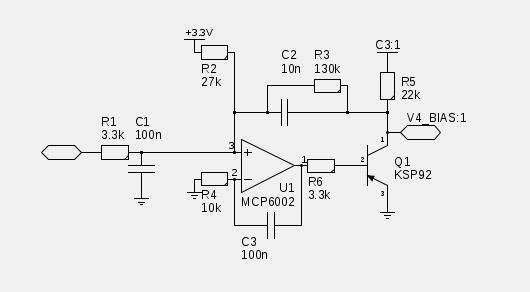
                          My bias circuit does it with PWM into an opamp error amp driving the base of a high voltage pnp transistor. Doing it this way you could use a single pot/encoder plus a selector. Opamp is some garden variety rail to rail opamp. The transistor isn't expensive. I have the error amp as a summing amp, which inverts and offsets (amazing what you can accomplish with a summing amp, it's almost an analog computer), so that 0V out is full negative rail

                          The micro I'm using cost no more than the arduino's ($14 on black friday), but it's a 48mhz 32 bit Arm processor, and it can do pwm at ultrasonic frequencies.


                          C3 is the negative rail. V4_Bias feeds the bias on the source follower driving the grids. I'm only using a single pole because my PWM frequency is way way higher than the 480Hz feeding the error amp. (I'm using a KSP92 because it's used elsewhere for my high voltage PNP's It's probably not ideal right here. Trading off some of the excess voltage spec will probably buy you some more goodness somewhere.)
                          Last edited by NateS; 12-10-2013, 02:31 AM.
                          The prince and the count always insist on tubes being healthy before they're broken

                          Comment


                          • #14
                            Originally posted by NateS View Post
                            For parameters that take loctite purple, as opposed to all out fiddly user interface, if there's a micro involved, I would set those parameters via serial interface, and store them in eeprom. Get rid of single use pots wherever possible.
                            Yep. I think the tech chasm would be a problem to many tech-naive ampsters, though. Perhaps a "memorize this now" button where it would not again depend on the pots.

                            Originally posted by Enzo
                            You say "bias is critical" but I am not sure what you mean. It is critical the bias be there, but in my mind it is not critical in the sense of " it must be exactly 38.0946ma per tube" or some such.
                            You are right. I was speaking "critcally" of it being there and not subject to abrupt failures. And six-digit accuracy is indeed far from useful. The hidden advantage of a three-lights indicator is that it does in fact hide the extra decimal places - which, as we know, are dependent on the meter that reads it.
                            And I point that out because the "precision" of a 10-turn pot is just silly in my view, the bias does not need that. A single turn twiddle pot works just fine.
                            Yeah. Notice I caved on that one pretty quickly.

                            Originally posted by Enzo
                            As to running the whole bias voltage across the trimmer so it dissipates half a watt, well...
                            I don't recall which Fender amp we drew the example from, but when I suggest ways to make bias adjustable on some amp, and the solution is to make a 47k resistor variable, I also suggest they not install a 47k pot, but rather a 25k pot and a 22k resistor in series or even a 10k pot and a 33k or 39k resistor in series. The full range of voltage adjustment is not needed usually, so now instead of a large voltage across a pot, we have a much smaller voltage across a pot.
                            Yeah, I'll go for that. The fender I used was a super reverb. There are probably other examples. The circuit I have drawn has built-in series resistors on both ends of the pot so it can be customized, but I was doing a bit of stealth idiot-tolerance in case some ...er, naive person... elected to leave the resistors out or replace them with wires.

                            ALternatively, instead of looking for a hefty pot, could be not use the trimmer to control a transistor current? Thus the trimmer can be puny, the transistor is the part that dissipates.
                            Yeah, could do that. But then I have to have the 473rd version of the argument with the people who think that if silicon is within ten feet of their amp, it ruins the tone somehow. And the people who will leap in with the comments that semiconductors are less reliable than resistors. And the rest of that mess. I must be getting old, avoiding a fight. At least I know where the fights are.
                            Originally posted by Gingertube
                            I do use 10 turn pots - not for the precision in idle current setpoint, but for simple reliabilty. Yes the pots are more expensive but they are far better built too and so less prone to failure. Addressing bias pot failure with a "safety" resistor from wiper to full -ve bias supply is a good idea but it still leaves you with a faulty board which will require a fix.
                            Hmmm. An other vote for transistors. Let's take a step sideways guys.

                            The grid resistors are normally 100K to 220K, set by the manufacturer's recommendation to prevent runaway in most cases. The impedance at the bias end of the grid leak resistor has to be no more than ________________________ [you fill in that blank] to keep them from running away.

                            Nate, you have come up with almost exactly the circuit I used in the analog portion of the uC controlled circuit I used, right down to the high voltage PNP.

                            I personally really like having the end of the bias pot having a phillips screwdriver hollow in it.

                            I'm a little chagrined at these turns, because the problem I'm really trying to solve has no dependence on the bias pots or circuits whatsoever - it just tells you too cold, too hot, just right, and waaaaay too hot for too long.

                            Ah, well, back to the virtual drawing board.
                            Amazing!! Who would ever have guessed that someone who villified the evil rich people would begin happily accepting their millions in speaking fees!

                            Oh, wait! That sounds familiar, somehow.

                            Comment


                            • #15
                              I wasn't suggesting ditching the pot all together. Just use one pot, feeding one of your analog inputs, and a selector knob. Select the tube you wish to tweak. Tweak away with desired implement. When you leave it alone long enough it saves the value.

                              Maybe Tube Selector, Bias Tweaker, and another trimpot for the delay on lighting the "OK, Now Panic" sign.
                              The prince and the count always insist on tubes being healthy before they're broken

                              Comment

                              Working...
                              X