Announcement

Collapse
No announcement yet.

Measuring impedance of coils and speakers

Collapse
X
 
  • Filter
  • Time
  • Show
Clear All
new posts

  • Measuring impedance of coils and speakers

    First of all, I would like to apologise for asking such a broad area of field type question. I'm struggling to understand the basics.
    So lets begin.
    I was thinking of measuring the impedance of a coil. So I measure the square wave output of my old LC meter in its inductance measure mode. This measures 900Hz. Then I connect my meter to the inductor, and take the reading in Henries, and use XL=2*pi*F*L to determine impedance (reactance)
    Anything wrong with this method?
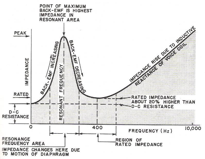
    Can this method be used for speakers too?
    I read somewhere that I will need a LRC meter to do this...
    What factors am I missing here?
    Please help a complete noob understand. Thank.

  • #2
    Diydidi,

    Look at this web link. http://www.diy-audio.narod.ru/litr/Le.pdf

    Speakers, because they move, have a complex impedance at various frequencies. This paper discusses the inductance Le; the e stands for effective due to the complex nature of the mechanics of a moving speaker. Typically, an 8 ohm rated speaker will measure near 6 ohms DCR.

    I hope this gets you moving in the right direction.

    Joseph J. Rogowski

    Comment


    • #3
      Speakers, because they move, have a complex impedance at various frequencies.
      This. The voice coil itself is pretty much just an inductor with moderately high series resistance.

      But because the assembly is actually electromechanic the motion causes both inductive and capacitive characteristics to loading. In fact, these characteristics interact together as a resonant system.


      So, you have voice coil resistance as minimum impedance, inductance increasing impedance towards higher frequencies and an impedance peak at resonant frequency. Cabinet will also impart some characteristics, at least in acoustic suspension or vented schemes.

      Thanks to Olson, Thiele, Small and other inventive gentlemen we, however, have some pretty good analogies to model such electromechanic systems.

      Comment


      • #4
        This picture is correct.

        BTW, this ratio is used to measure the resonant frequency of the speaker in free air.

        Speaker is connected to the audio generator in series with a resistor about 100 Ohm
        (in order to exclude impact of low output impedance of the signal source).
        Multimeter measuring AC voltage is connected to the speaker.

        Find the maximum value of the voltage by varying the frequency of the generator within the 20-200 Hz. The frequency corresponding to this maximum is the resonant frequency of this speaker in free air.

        Comment


        • #5
          Looking at the graph teemuk posted, it would seem the rated impedance of the speaker will be in the region just after the resonant frequency in free air. Seems like here in this region the voltage across the speaker stays relatively constant for a while.
          So is it then a question of using ohms law to calculate the speaker impedance? Zspk=Vspk/(I through 100ohm res)

          Comment

          Working...
          X