Announcement

Collapse
No announcement yet.

ecc99 low powered amp

Collapse
X
 
  • Filter
  • Time
  • Show
Clear All
new posts

  • ecc99 low powered amp

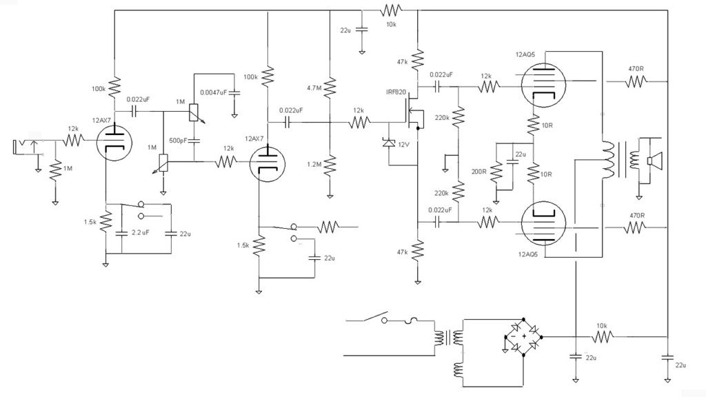
    I'm thinking of making a small amp for home/recording using an ecc99 for the output tube. I'm limited by what I have in my junk pile which leaves me with looking at the following topology using two 12ax7s and an ecc99:

    Input > 1st stage > gain pot > 2nd stage > CF > FMV tone stack > cathodyne PI > ecc99 power amp.

    My concern is that there might not be enough swing left after the TS to get enough out of the cathodyne to drive the ecc99 so I may have to rethink things. Should I really be looking at using a recovery stage before the cathodyne as is typically found? If so I may use a mosfet source follower in place of the CF to free up a triode for this purpose. I'm not against using a mosfet but if I can use the CF I'd prefer that as I'd like to play around with the cathode load resistor value to dial in the right amount of compression which I guess doesn't work using a mosfet.

    Thoughts?

  • #2
    How about you use the MOSFET for the cathodyne stage instead of the CF?
    Experience is something you get, just after you really needed it.

    Comment


    • #3
      That sounds like an interesting solution. I've had a quick scout but I've not seen any well tested circuits. Do you know of any I could take a look at?

      Comment


      • #4
        Originally posted by Zozobra View Post
        That sounds like an interesting solution. I've had a quick scout but I've not seen any well tested circuits. Do you know of any I could take a look at?

        Something like this should work. The FET is isn't very critical. It has to withstand the B+ and dissipate up to 300mW.
        Attached Files
        Last edited by nickb; 01-12-2016, 05:52 PM.
        Experience is something you get, just after you really needed it.

        Comment


        • #5
          Thanks. I'll have a play with that

          Comment


          • #6
            Well this is timely. Just been playing with a mosfet in the cathodyne position. Figured a 12AX7 will handle the gain duties and since the cathodyne really does not add much to the sound of an amp, unless it messes it up, might as well use a SS device there.


            The above looks much better than the board, just sort of winged it and found I could have used an extra inch.


            I have to change the tone control section in the amp, the above schematic will be the completed one. I am adding the NFB switch, not in it yet but otherwise the amp works and behaves fine. Basically one of the Tweed Fenders (Harvard, Princeton, Vibrolux) although lower voltage and no tremolo. No issues found using the IRF820, used it as it is about the most common device of its type used by guitar amp tinkerers. This is my $100 amp design, came out in response to a diyAudio challenge from years back.

            Comment


            • #7
              @nickb,

              Your schem has resistor R4 added to the basic Mosfet source follower design that I've seen. Care to explain why it's there?

              edit: OK, nvm. I see that it's fixed bias -ish. Could you remove C3 and R4 and have it DC coupled?
              If it still won't get loud enough, it's probably broken. - Steve Conner
              If the thing works, stop fixing it. - Enzo
              We need more chaos in music, in art... I'm here to make it. - Justin Thomas
              MANY things in human experience can be easily differentiated, yet *impossible* to express as a measurement. - Juan Fahey

              Comment


              • #8
                Originally posted by eschertron View Post
                @nickb,

                Your schem has resistor R4 added to the basic Mosfet source follower design that I've seen. Care to explain why it's there?

                edit: OK, nvm. I see that it's fixed bias -ish. Could you remove C3 and R4 and have it DC coupled?
                R4 is to protect against oscillation - like a grid stopper. You can DC couple the input but the DC level would need to be right. You want to get about 1/4 to-1/3 of the supply across the source resistor. I used a potential divider to side-step the unknown. Printer2 improved on the basic idea by feeding the bias divider from after an extra stage of ripple rejection, something I wasn't thinking about.
                Experience is something you get, just after you really needed it.

                Comment


                • #9
                  Thanks guys. This will be most useful for this build and I look forward to trying it out
                  Out of interest what is the input sensitivity of the circuit and what sort of swing can it output?

                  Comment


                  • #10
                    Originally posted by Zozobra View Post
                    Thanks guys. This will be most useful for this build and I look forward to trying it out
                    Out of interest what is the input sensitivity of the circuit and what sort of swing can it output?
                    The gain is slightly less than unity. The max Vpp swing is a bit less than half of the supply rail if you arrange bias so that that 1/4 of the supply is dropped across the source resistor. I actually went to 1/3 of supply across the source resistor since you didn't need a big swing and so reduce the power dissipated in the FET.
                    Experience is something you get, just after you really needed it.

                    Comment


                    • #11
                      I think it split to 20% the supply, I think I had about 200V at that point and 40V across the resistors. You can adjust the voltage divider as you like. Can't take any credit for the circuit, been around for a while but I never seen much about someone using it. I think I may have had 30V out of it, could be more.

                      Oh shoot, my filter section is wrong, I have it upstream of the filter. Oh well, will work either way.

                      Comment


                      • #12
                        A popular FET for replacing triode stages is the LND150. It's depletion mode which means it can be used without any special biasing; just use it exactly as you would a triode (without the heaters). Works for most common uses of a triode stages in guitar amps. For example, I believe Marshall uses it in place of the cathode follower in some of the anniversary 1 watt amps.

                        If you're a triode stage short, I would try an LND150 as the first gain stage, or as cathode follower (technically it becomes a source follower).

                        Comment


                        • #13
                          Originally posted by nickb View Post
                          R4 is to protect against oscillation - like a grid stopper. You can DC couple the input but the DC level would need to be right. You want to get about 1/4 to-1/3 of the supply across the source resistor. I used a potential divider to side-step the unknown. Printer2 improved on the basic idea by feeding the bias divider from after an extra stage of ripple rejection, something I wasn't thinking about.
                          I'm zeroing in on it now. I've used Mosfets as source followers where I wanted a (clean!) impedance buffer, but hadn't seen the cathodyne application. So yes, getting the grid voltage right for optimizing split phase waveforms would be a trick with DC coupling. Thanks!
                          If it still won't get loud enough, it's probably broken. - Steve Conner
                          If the thing works, stop fixing it. - Enzo
                          We need more chaos in music, in art... I'm here to make it. - Justin Thomas
                          MANY things in human experience can be easily differentiated, yet *impossible* to express as a measurement. - Juan Fahey

                          Comment


                          • #14
                            I'm now thinking about this project a little differently. In all honesty I probably need another amplifier like I need another hole in my head as I have already have quite a few that don't see the sort of play time they should as they're all 100W beasts and not really home friendly. I then got thinking about the Fryette power station, which by most accounts is a decent bit of kit, as a review cropped up on a forum I frequent. At first glance this looks to not be too much more than a resistive dummy load feeding a valve power amp - I certainly can't see any great big choke/inductors in there to indicate a reactive load it used.

                            So I'm thinking why not do the same but with a small power amp such as this? It would make my big amps useful and I need to make a high powered dummy load anyway. Doodles to follow.

                            Comment


                            • #15
                              Originally posted by printer2 View Post
                              Well this is timely. Just been playing with a mosfet in the cathodyne position. Figured a 12AX7 will handle the gain duties and since the cathodyne really does not add much to the sound of an amp, unless it messes it up, might as well use a SS device there.


                              The above looks much better than the board, just sort of winged it and found I could have used an extra inch.


                              I have to change the tone control section in the amp, the above schematic will be the completed one. I am adding the NFB switch, not in it yet but otherwise the amp works and behaves fine. Basically one of the Tweed Fenders (Harvard, Princeton, Vibrolux) although lower voltage and no tremolo. No issues found using the IRF820, used it as it is about the most common device of its type used by guitar amp tinkerers. This is my $100 amp design, came out in response to a diyAudio challenge from years back.
                              Hope you don't mind me adding this to your thread. Don't want to start a new thread just for this amp, just wanted to throw in a last picture. Chassis is a that was a cover for a box, just roughly

                              Comment

                              Working...
                              X