Announcement

Collapse
No announcement yet.

Traynor YBA-1A lowering the plate voltage

Collapse
X
 
  • Filter
  • Time
  • Show
Clear All
new posts

  • Traynor YBA-1A lowering the plate voltage

    Been having tons of fun modding my YBA 1 Mark II ,but to take some voltage down a little & heat off the tubes .i've read that lowering the voltage with Zener diodes can do the trick .
    any one have success with this ?
    i was suggested to try upping the value on the screen resistor by separating the single resistor to two separate 1Kohm 5watt ones.
    I did find a thread on the Marshall forum with the pic ,the user used the zeners on a strip
    any one please feel free to chime in

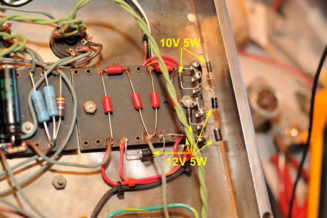
    Traynor YBA-1 at high plate voltage | Page 2 | MarshallForum.com
    "UP here in the Canada we shoot things we don't understand"

  • #2
    What does your plate voltage measure?
    If your amp is running EL34s, they are high voltage tubes.
    1k ohm 5 watt resistors is pretty much the standard screen resistors for EL34s.

    T
    "If Hitler invaded Hell, I would make at least a favourable reference of the Devil in the House of Commons." Winston Churchill
    Terry

    Comment


    • #3
      560+ or more
      OLD 6CA7's & was going to go with the modern JJ 6ca7's
      "UP here in the Canada we shoot things we don't understand"

      Comment


      • #4
        I agree that the 6CA7s are a good choice.
        They have a 800V plates, and allow 500V on the Screens.
        5W resistors are cheap, get some 1K, 1.5k, and 2k resistors, and try them out.
        Run the highest resistor value that still sound ok.
        If the Preamp voltage is too high, you can tune that with B+ rail dropping resistors.
        Other than that, you may want to leave the PT plate voltage as is.
        GL,
        T
        https://d1sjrnpi226dnf.cloudfront.ne...pdf?1383163032
        "If Hitler invaded Hell, I would make at least a favourable reference of the Devil in the House of Commons." Winston Churchill
        Terry

        Comment


        • #5
          I got to locate that resistor in my amp ,getting a order ready ,I'm assuming they are the ceramic type
          Last edited by copperheadroads; 09-12-2016, 08:45 PM.
          "UP here in the Canada we shoot things we don't understand"

          Comment


          • #6
            Just finished one of these over Memorial day weekend. Here is some of what i wrote on another website.

            Wired 99% a plexi marshall, split cathode, added a choke, screen grid resistors, high voltage fuse, master volume ( with 4 caps) , outside bias adjust with measuring points, .68uf on V2 cathode, bright cap clipped, iec power cord, new EH 6ca7's.

            Tests on the bench reveal 122 watts when clipping, 82 watts clean. The plate voltages are 580 and screen 556. 30 ma plate current. I measured screen current and am within limits because that's what melts when you crank it.

            Pictures below. Oh yeah, the tube stash of 12ax7s and 12au7s and misc. I can actually get more watts out with a 12at7 in the PI, than a 12ax7. Gain is less but when you crank the volume you can get out more power. With the master volume lower, the 12at7 pushes more current. The best were 5965's and 6201's GE gray plate. Any gain with black plates, clear tops, telefunkens, amperexs and mullards were all slightly lower, this is all in the PI section. Will tube roll the preamp once the neighbors leave for the holiday.


            Click image for larger version

Name:	1741432077514815.jpg
Views:	1
Size:	197.5 KB
ID:	843565
            Click image for larger version

Name:	174203-143402900.jpg
Views:	1
Size:	139.8 KB
ID:	843566

            Comment


            • #7
              Originally posted by mozz View Post
              Will tube roll the preamp once the neighbors leave for the holiday.
              In my own experience the louder I play the sooner my neighbors leave...

              Steve A.
              The Blue Guitar
              www.blueguitar.org
              Some recordings:
              https://soundcloud.com/sssteeve/sets...e-blue-guitar/
              .

              Comment


              • #8
                I'm assuming this is the shared screen resister 470ohm 10 watt that i have circled in the schematic
                "UP here in the Canada we shoot things we don't understand"

                Comment


                • #9
                  Yes, that is it.
                  Originally posted by Enzo
                  I have a sign in my shop that says, "Never think up reasons not to check something."


                  Comment


                  • #10
                    If you want to do individual 5w resistors, you could follow the Plexi 50w layout!
                    http://site.triodestore.com/50WPlexiLayout.pdf
                    T
                    "If Hitler invaded Hell, I would make at least a favourable reference of the Devil in the House of Commons." Winston Churchill
                    Terry

                    Comment


                    • #11
                      There is really 2 in series. I just put them right on the socket (1k) and left a 470 after the B+ (and choke 10-15H). Mouser sent me 13w instead of 10w. The resistors (470) as i recall were measuring low, about 430 so maybe the ceramic type get shorted turns as they age with heat.

                      Doesn't the center tap resistor or zener trick raise the power supply impedance? I used the choke because i had 1 here and wanted to follow the Marshall schematic as close as i could.

                      Also check out that power resistor 150k that go to the bias supply, that was out of tolerance too, also change bias caps of course. There are many revisions to that schematic, later ones have adjustable bias as well and a few other things. Remove those diodes (not actual diodes but i forget the name) across the output tube plates, they short or leak over time.

                      Comment


                      • #12
                        Originally posted by mozz View Post

                        Doesn't the center tap resistor or zener trick raise the power supply impedance? I used the choke because i had 1 here and wanted to follow the Marshall schematic as close as i could.

                        Also check out that power resistor 150k that go to the bias supply, that was out of tolerance too, also change bias caps of course. There are many revisions to that schematic, later ones have adjustable bias as well and a few other things. Remove those diodes (not actual diodes but i forget the name) across the output tube plates, they short or leak over time.
                        I don't think the zener adds appreciable impedance because the diode itself has very little resistance. That's why it's done, to not introduce the extra resistance for added sag like a resistor will. I usually add zener(s) in series with the B+ rail after the bias tap, not in the CT.

                        As long as you mention the bias 150k resistor, this brings up another subject. The lowering of the B+ with the CT zener/resistor will also lower(less negative) the bias voltage by the same amount as the B+ is lowered, so this needs to be kept in mind. Lowering the B+ to the power tubes will require less negative bias, so it just might even out. Just something to be aware of.
                        Turn it up so that everything is louder than everything else.

                        Comment


                        • #13
                          There was also a issue of noise when adding zeners etc.etc. That's another topic though. I have seen some nice zig zag zener add on boards, the 5 watt aren't too big and you can tap the drop you need. I think if he adds 1k to the screens, and maybe a 470 from the b+, he will be fine, depends on the voltages. I don't run mine 24/7 so i can't speak of long term. Others will know what brand tube is best in this situation.

                          Actually i go by the filament voltage, if it's a lot higher than 6.3v then i know i have to bring them all down. Often add a .1 or .22 to drop the filament and then measure the rest.

                          Comment


                          • #14
                            Originally posted by Steve A. View Post
                            In my own experience the louder I play the sooner my neighbors leave...

                            Steve A.
                            My neighbors easily know when my wife is not home ,the Guitars get so much louder ..
                            "UP here in the Canada we shoot things we don't understand"

                            Comment


                            • #15
                              Originally posted by mozz View Post
                              Remove those diodes (not actual diodes but i forget the name) across the output tube plates, they short or leak over time.
                              Those are TVS (transient voltage suppressor) diodes, and yes, best to remove them. If memory serves, they are brown rectangular box like things. If desired, they can be replaced by modern spike protection diodes as used in Peavey, Fender, etc.

                              Originally posted by mozz View Post
                              Actually i go by the filament voltage, if it's a lot higher than 6.3v then i know i have to bring them all down. Often add a .1 or .22 to drop the filament and then measure the rest.
                              I mentioned this to Copperhead on another forum. If heater is high, I would recommend dropping incoming line voltage using a bucking transformer ala RG Keens vintage voltage adapter.
                              Copperhead, can you post the heater voltage you are getting? Is it much more than 6.3V with all tubes installed? In my part of Canada we have hot line voltage, never less than 124V so this can be a big issue.
                              Originally posted by Enzo
                              I have a sign in my shop that says, "Never think up reasons not to check something."


                              Comment

                              Working...
                              X