Announcement

Collapse
No announcement yet.

My guitar Pre-Amp stage/filtering and STM32F4

Collapse
X
 
  • Filter
  • Time
  • Show
Clear All
new posts

  • My guitar Pre-Amp stage/filtering and STM32F4

    I am currently involved in an academic project which the topic is to design a Digital Tuner for Electric Guitars. My knowledge of electronic is very basic, so here I am.

    I need to pre-process the signal that goes out from the pickups of a common electric guitar, let's consider passive pickups so....we have an output voltage from 200mV up to 1V of peak, with also negative peaks (of the same magnitude).

    I have to use the STM32F4 (Discovery Board), so I need a very simple circuit that drives the On-Board 12-bit ADC, that takes, as inputs, signals with voltage between 0 and 3.3V. So I have to design a pre-amp circuit that amplifies and clamps the guitar's output.

    I want to underline that I have never realized an electronic circuit (a real one, not in the simulator) before. I am wondering about:

    STM32F4 provides some voltage sources (5v or 3v). Shall I use these sources or is it preferable to go with an external voltage source (e.g., batteries)?
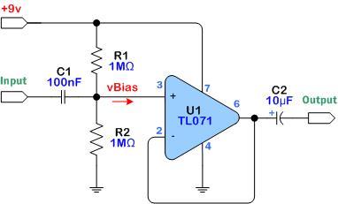
    I have chosen an opamp that is not, let's say, "handy" because it needs 2 voltage sources: the TL082. What op-amp do you suggest me to use? (maybe with only 1 voltage source)
    I have tried to design a circuit by using LTSpice, but I don't know if it is correct at all. You can also notice that I have inserted a filtering stage (LP w/ cutoff freq. 2,2 KHz) and a "protection" Schottky diode before entering in the pin of the board.
    Click image for larger version

Name:	IDsG5.png
Views:	1
Size:	39.2 KB
ID:	871033

  • #2
    Look at various effect pedals, they mostly run on one battery. The op amps runs on +12 and -12 volts, but +24 and zero (ground), puts the same 24v across the op amp. In the case of 9v pedals we use +9 and ground. we then make a zero reference by putting two large resistors in series across teh 9v, the center point becomes "zero" a pair of 100k works. The op amp is now effectively running on +4.5 and -4.5.
    Education is what you're left with after you have forgotten what you have learned.

    Comment


    • #3
      This is one example of what Enzo means:


      1) the Op Amp is biased by 2 1M rsistors.
      2) both input and output sit at 1/2 Vcc , the power supply voltage, which here is 9V, so they sit at half that, some 4.5 V dc above ground
      3) input needs a DC blocking capacitor, C1, to separate that from the guitar pickup and pots.
      4) in normal, "audio" use output also needs a DC blocking capacitor, but in your case I guess your ADC input expects some always positive DC varying voltage (which has the audio superimposed), between 0 and 5V DC.
      In this case voltage can vary between 0 and 9V DC (battery voltage) but no big deal to correct that:
      a) do not use the output capacitor C2 but connect Op Amp output, pin 6, to ground through 2 series resistors, say 2200 or 4700 ohms each ,your digital friendly output will be taken from the middle point between them, and now can swing between 0 and 4.5V ... what the doctor ordered

      In fact it will swing a little less, but itīs irrelevant.
      As of gain, leave it as is: a unity gain buffer, because guitar pickups, specially if humbuckers, can easily produce more than 1V peak if strummed hard.
      Juan Manuel Fahey

      Comment


      • #4
        Originally posted by Enzo View Post
        Look at various effect pedals, they mostly run on one battery. The op amps runs on +12 and -12 volts, but +24 and zero (ground), puts the same 24v across the op amp. In the case of 9v pedals we use +9 and ground. we then make a zero reference by putting two large resistors in series across teh 9v, the center point becomes "zero" a pair of 100k works. The op amp is now effectively running on +4.5 and -4.5.
        Yes.various effect pedals run on one battery.Thanks a lot!

        Comment


        • #5
          Originally posted by J M Fahey View Post
          This is one example of what Enzo means:


          1) the Op Amp is biased by 2 1M rsistors.
          2) both input and output sit at 1/2 Vcc , the power supply voltage, which here is 9V, so they sit at half that, some 4.5 V dc above ground
          3) input needs a DC blocking capacitor, C1, to separate that from the guitar pickup and pots.
          4) in normal, "audio" use output also needs a DC blocking capacitor, but in your case I guess your ADC input expects some always positive DC varying voltage (which has the audio superimposed), between 0 and 5V DC.
          In this case voltage can vary between 0 and 9V DC (battery voltage) but no big deal to correct that:
          a) do not use the output capacitor C2 but connect Op Amp output, pin 6, to ground through 2 series resistors, say 2200 or 4700 ohms each ,your digital friendly output will be taken from the middle point between them, and now can swing between 0 and 4.5V ... what the doctor ordered

          In fact it will swing a little less, but itīs irrelevant.
          As of gain, leave it as is: a unity gain buffer, because guitar pickups, specially if humbuckers, can easily produce more than 1V peak if strummed hard.
          Oh! I see! I know what you mean.Thank you!

          Comment

          Working...
          X