 Tweet
Tweet
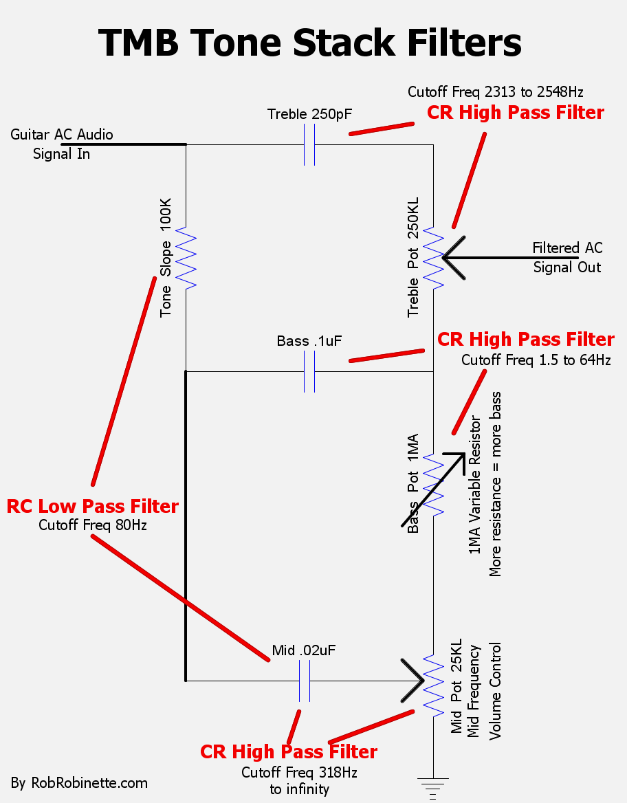
I'm working on a How the TMB Tone Stack Works webpage and I'm stretching at the limits of my knowledge and understanding of audio circuits. I know many of the sharpest tube amp audio minds in the world hang out here so I'm asking if you could review the webpage for accuracy and suggestions before I release it into the wild. Thank you in advance.
Sample graphics:
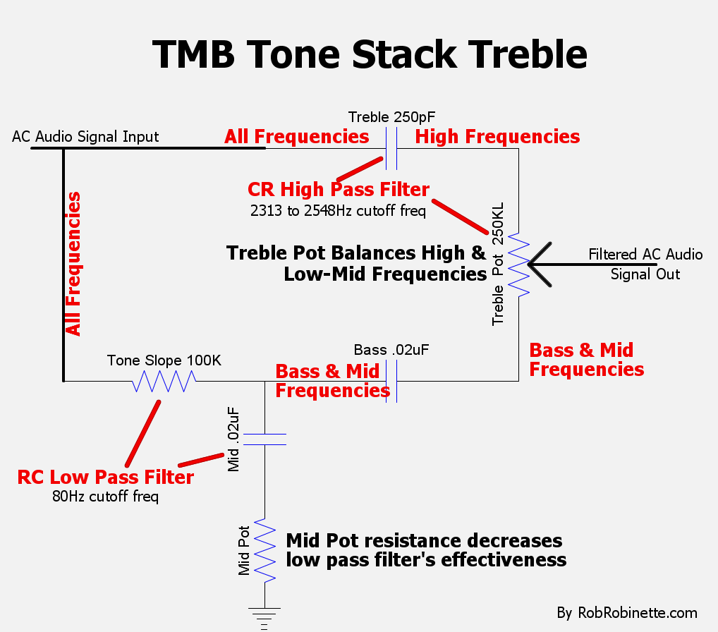
Sample graphics:
Comment