Announcement

Collapse
No announcement yet.

Phase Inverters with CCS

Collapse
X
 
  • Filter
  • Time
  • Show
Clear All
new posts

  • Phase Inverters with CCS

    Hi all,

    I open this thread because I would like to talk about phase inverters with constant current sinks. Few designs apply them in the guitar world, and I think there can be more to squeeze from it with the partecipation of all of us.

    I've recently bought a Marshall 9200, and I re-jumped in the PIs with CCS world were I've been years ago with the Mesa Boogie 295 Simul Class.

    While fixing some weak points of the 9200 project (mainly bias and NPN for the CCS), I've done some simulations on the possibility to do some small improvements on the design of the PI.

    Well, the advantage of the CCS is (close to) infinite AC impedance (good for PI balance) while DC current flows as per the circuit setup. In the case of the Marshall 9200 circuit, the current is:
    0,7 V / 270 Ohm = 2,6 mA

    The concept is the same described here:


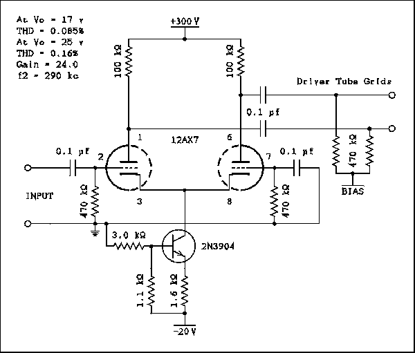
    Lets say the collector current tries to increase. The emitter current will also try to increase which makes the drop across the 1.6 k ohm resistor increase. Because the base voltage is held very constant by the voltage divider of the 3 k and 1.1 k ohm resistors the bias on the base-emitter junction will be decreased. This will decrease the base current and cancel out most of the collector current increase. The collector current has to change by a small amount to make the base current change, but the change is very small. The collector current is 3 mA and most 3904s have a current gain of more than 100 so the base current is about, or less than, 30 microamps. The divider current is 4.88 mA. The base current is 0.615% of the divider current.
    As you can see the distortion was very low, much lower than I had expected. Also the distortion at both outputs was very similar. When feedback was simulated the balance remained perfect. The distortion changed though. The plate on the left gave 0.09% while the right hand plate gave 0.175%. This low level of distortion means the distortion imbalance can be disregarded.
    Practical Phase Inverters.

    This configuration has in fact very low distortion, with a bit of a prevalence of 3rd harmonic.

    By looking at this other configuration by Crowhurst:


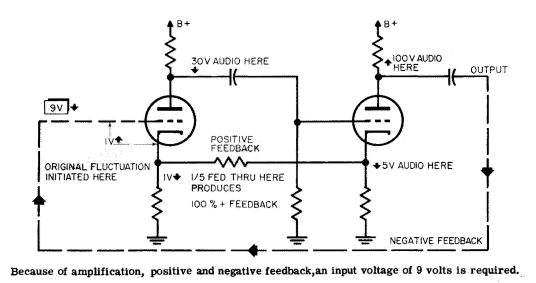
    Positive feedback can only be used over one stage in order to avoid oscil-
    lation. An easy way to accomplish this positive feedback is to couple cathode
    bias resistors of two consecutive stages in the earlier part of the amplifier,
    where the distortion is small.

    A momentary positive fluctuation at the grid of the first stage will pro-
    duce a momentary negative fluctuation at the plate, which is passed on to
    the grid of the following stage. This produces another positive fluctuation
    at the plate of the second tube. At the same time, the negative fluctuation
    at the plate of the first tube, resulting from increased plate current, will be
    accompanied by a positive fluctuation at its cathode. Similarly, a negative
    fluctuation appears at the cathode of the second tube. The fluctuation at
    the cathode of the second tube is much bigger than that at the first stage.
    Connecting the resistor between the cathodes will allow some of the fluctua-
    tion from the cathode of the second stage to cancel the fluctuation at the
    cathode of the first stage.
    https://archive.org/stream/Crowhurst...sic_3_djvu.txt

    So I came out with this simple modification on the 9200 to apply the following:
    - center the plates of the PI at 2/3 of B+
    - increase the current capabilities of the PI
    - apply some positive feedback between input stage and PI
    - give more dynamic range to the PI

    Anyone has some experience on them, from direct design or as a user of one amp with this configuration?

  • #2
    Looking at similar configurations, I came into the 9005 poweramp:
    http://drtube.com/schematics/marshall/9005.gif

    Searching some more informations on that 9005 configuration and its origins, I've found that the Major had a similar configuration, with a concertina plus a differential amp based on a 12au7.

    Well, I've also found that the original schematics by Marshall are wrong, because the signal is taken from the cathode of the concertina, and the 1M resistor is also connected to the cathode of the concertina, even if the schematics say the opposite:
    http://drtube.com/schematics/marshall/1966u.gif
    http://drtube.com/schematics/marshall/1967u.gif
    http://drtube.com/schematics/marshall/1978u.gif

    Comment


    • #3
      Originally posted by Roberto View Post
      Hi all,

      I open this thread because I would like to talk about phase inverters with constant current sinks. Few designs apply them in the guitar world, and I think there can be more to squeeze from it with the partecipation of all of us. ...
      Anyone has some experience on them, from direct design or as a user of one amp with this configuration?
      I've built two amps with CCS in the PI. Full schemos are on my site, but these clips show the PI. The first (Princeton AOT) uses two EF86 tubes which is a bit crazy, but it was an experiment to see if screen voltage shifts could impact compression/tone at high drive levels. The CCS does balance things pretty well - the 500 ohm adjustment pot is helpful. However, tube variation with EF86's seems high so perfect matching is going to take some selection among a batch of tubes. The screen shifts do occur as hoped and the OD tone of this PI is good - although I can't say I've heard it in isolation. By the time the PI is in OD, there is distortion coming from other sources as well.

      Click image for larger version

Name:	P-AOTv3.jpg
Views:	1
Size:	130.5 KB
ID:	845226

      The second figure is from my current project (BML) and it uses a CCS with two triodes. Again, very good results in terms of balance and gain and OD behavior. This design has a great clean tone so I can attest to the PI behavior under high, but still linear range signals.

      Click image for larger version

Name:	BML PRE1b.jpg
Views:	1
Size:	209.3 KB
ID:	845227

      A point you didn't raise, but it seems a virtue of the CCS approach, is that it presents a great tremolo opportunity. The BML schem shows this. The trem osc drives the CCS to vary the PI tube current. The trem tone is smooth and very "bias-y" sounding.
      “If you have integrity, nothing else matters. If you don't have integrity, nothing else matters.”
      -Alan K. Simpson, U.S. Senator, Wyoming, 1979-97

      Hofstadter's Law: It always takes longer than you expect, even when you take into account Hofstadter's Law.

      https://sites.google.com/site/stringsandfrets/

      Comment


      • #4
        I have also done a CSS tail, just with a normal 12ax7 LTP circuit. In my case, I was using a low B+ and wanted to do without the huge voltage drop (and loss of swing) of a tail resistor. It seemed to work quite well, but I didn't try any A-B comparisons.

        Comment


        • #5
          A differential amplifier with only one input fed, the other held constant, amounts to a common cathode stage from the input to the first plate, but for the path from the input grid to the second tube, it is a common plate stage ( that is, a cathode follower ) feeding the second tube as a common grid stage with its output on the second plate.

          The low output impedance of the first tube stage's cathode pulls the second cathode up and down by nearly the same signal amount as the input grid moves, and since the second tube grid is held fixed, the second tube's cathode-to-grid voltage is wobbled about by the same signal as the first tube's grid-to-cathode, but the phase is inverted. So the plate signal of the second tube is **about** the same size/current as the first tube, but inverted in phase.

          That only holds true if the biasing elements on the shared cathodes don't eat any of the signal being pumped in through the first cathode. So the lower the impedance of the shared cathode biasing resistor, the more signal leaks out of the cathode1 to cathode2 path and the smaller the signal on the second tube's plate. Conversely, the higher the impedance of the biasing resistor on the two cathodes, the more the signal from the first cathode gets into the second cathode, and the closer the two signals on the plates are to the same magnitude.

          The classical diffamp PI in guitar amps usually tries to fix this up a bit by making the plate resistors of the two triodes different sizes to try to get the gains back to more similar sizes, even in the face of non-identical gains caused by low cathode biasing resistors.

          Biasing with a CCS is about as high an impedance as you can do for the shared cathodes without going to extreme measures. CCS biasing on the cathodes of a diffamp PI helps get the gains to be much closer. It can also make the usual tricks with feedback into the shared cathodes for "presence" and other stuff harder to do.
          Amazing!! Who would ever have guessed that someone who villified the evil rich people would begin happily accepting their millions in speaking fees!

          Oh, wait! That sounds familiar, somehow.

          Comment


          • #6
            Thanks uneumann,

            Originally posted by uneumann View Post
            I've built two amps with CCS in the PI. Full schemos are on my site, but these clips show the PI.
            can I kindly ask you to link them here? I cannot find them.

            The second figure is from my current project (BML) and it uses a CCS with two triodes. Again, very good results in terms of balance and gain and OD behavior.
            That's one of the point I was thinking at, the OD behaviour, thanks for this feedback.

            A point you didn't raise, but it seems a virtue of the CCS approach, is that it presents a great tremolo opportunity. The BML schem shows this. The trem osc drives the CCS to vary the PI tube current. The trem tone is smooth and very "bias-y" sounding.
            That's something I never thought about. I will develop it following your indications.

            Comment


            • #7
              Originally posted by octal View Post
              I have also done a CSS tail, just with a normal 12ax7 LTP circuit.
              Thanks octal, what about its OD performance? How was NFB connected?

              Comment


              • #8
                Originally posted by R.G. View Post
                Biasing with a CCS is about as high an impedance as you can do for the shared cathodes without going to extreme measures. CCS biasing on the cathodes of a diffamp PI helps get the gains to be much closer. It can also make the usual tricks with feedback into the shared cathodes for "presence" and other stuff harder to do.
                Thanks R.G., AFAIK the second input is used grounded as a NFB input, including the presence pot. But I think I've missed something on your post, because I know you are well knowledged.

                Comment


                • #9
                  I was speaking more generally than just your circuit. The common string of resistors from the joined cathodes to ground is often used as an input for feedback from the OT secondary, as well as a tinkering point to add "presence" and other things by feedback.
                  Amazing!! Who would ever have guessed that someone who villified the evil rich people would begin happily accepting their millions in speaking fees!

                  Oh, wait! That sounds familiar, somehow.

                  Comment


                  • #10
                    Originally posted by Roberto View Post
                    Thanks uneumann,

                    can I kindly ask you to link them here? I cannot find them.

                    That's one of the point I was thinking at, the OD behaviour, thanks for this feedback.

                    That's something I never thought about. I will develop it following your indications.
                    Sure - the first circuit fragment is from version3 of this amp (scroll towards the bottom of the page) ...
                    https://sites.google.com/site/string.../princeton-aot

                    The second circuit is from this amp ...
                    https://sites.google.com/site/string...m-lite-project
                    “If you have integrity, nothing else matters. If you don't have integrity, nothing else matters.”
                    -Alan K. Simpson, U.S. Senator, Wyoming, 1979-97

                    Hofstadter's Law: It always takes longer than you expect, even when you take into account Hofstadter's Law.

                    https://sites.google.com/site/stringsandfrets/

                    Comment


                    • #11
                      Originally posted by Roberto View Post
                      Thanks octal, what about its OD performance? How was NFB connected?
                      I didn't use any NFB. OD performance was good, I adjusted the current in the CSS with a trimpot for best sound. I used the "Valve wizard" circuit.

                      The Valve Wizard (scroll down to the bottom, the very bottom circuit with the three biasing diodes in series is the one I used.) I substituted a trimpot for the 600 ohm emitter resistor. If I recall correctly, I had to go up in value a fair bit from what is shown in the schematic.

                      Comment


                      • #12
                        Originally posted by octal View Post
                        I adjusted the current in the CSS with a trimpot for best sound. I used the "Valve wizard" circuit.
                        Is there any technical reason to use three 1n4148 instead of two, and just Iccs = 0,6 V / Rk ?

                        Comment


                        • #13
                          Originally posted by uneumann View Post
                          Sure - the first circuit fragment is from version3 of this amp (scroll towards the bottom of the page) ...
                          https://sites.google.com/site/string.../princeton-aot
                          https://1617738a-a-62cb3a1a-s-sites....-aot/P-AOT.png
                          Thanks for sharing, I will take a deep look at it!

                          The second circuit is from this amp ...
                          https://sites.google.com/site/string...m-lite-project
                          https://1617738a-a-62cb3a1a-s-sites....ML%20PRE1b.png
                          This is more common to what I had in mind, and the bias shifting is really a nice plus!

                          Comment


                          • #14
                            Originally posted by Roberto View Post
                            Is there any technical reason to use three 1n4148 instead of two, and just Iccs = 0,6 V / Rk ?
                            It seems that it is explained in the article your are referring (starting from: "Note, this circuit may not work if Re is less than about 400 ohms.....").

                            Mark

                            Comment


                            • #15
                              Originally posted by Roberto View Post
                              Is there any technical reason to use three 1n4148 instead of two, and just Iccs = 0,6 V / Rk ?
                              Just a comment about the valve wizard circuit. It works fine for small signal PI drive conditions. But - if the PI is fed large signals to overdrive it, the shared cathodes swing negative to the point where the CCS saturates and no longer behaves as a CCS. That will change OD waveforms - you'll have to try it to see if you like it. A small reference voltage can keep the CCS out of saturation. Your OP shows a -20v supply. In my circuits, I use a small regulator (12v or 15v) to accomplish the same goal. You just want to create some headroom for the cathodes to swing without saturating the CCS.
                              “If you have integrity, nothing else matters. If you don't have integrity, nothing else matters.”
                              -Alan K. Simpson, U.S. Senator, Wyoming, 1979-97

                              Hofstadter's Law: It always takes longer than you expect, even when you take into account Hofstadter's Law.

                              https://sites.google.com/site/stringsandfrets/

                              Comment

                              Working...
                              X