Announcement

Collapse
No announcement yet.

Help Me Understand the LM386 Chip Amp

Collapse
X
 
  • Filter
  • Time
  • Show
Clear All
new posts

  • Help Me Understand the LM386 Chip Amp

    I have a How the Ruby Amp Works webpage and I would like to go into some detail of how the LM386 chip functions on the guitar audio signal. As many of you know I'm a tube guy and I'm pretty weak on solid state theory.

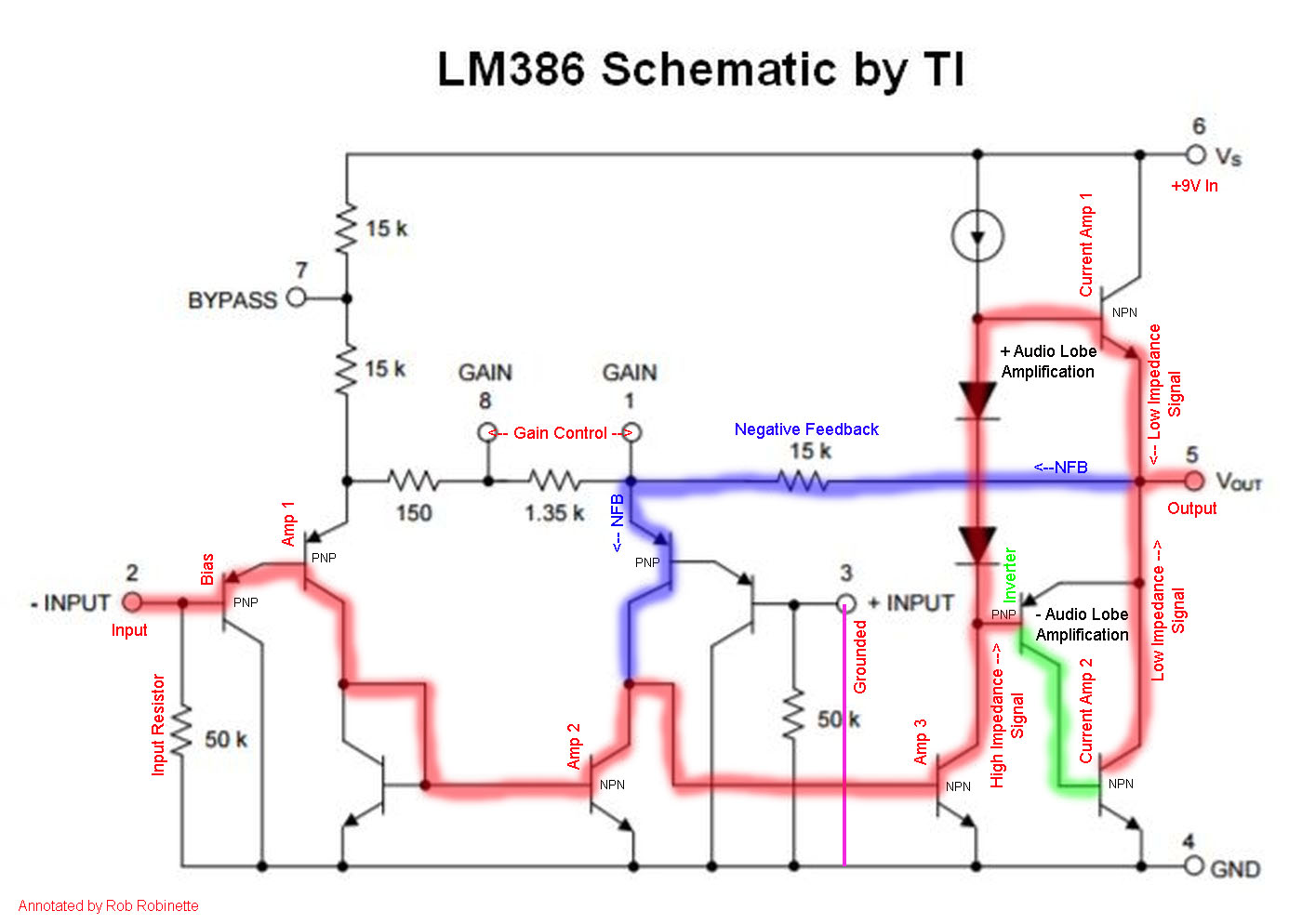
    The annotated schematic below is my first attempt to describe what each transistor in the LM386 is doing to the audio signal. Please look it over and let me know what I have wrong.

    Keep in mind in the Ruby Amp pin 3 (+ input) is grounded and only input pin 2 is used.

    The red line is the guitar signal path through the chip.

    Is it correct to call all 10 of the transistors in the LM386 op-amps?

    Last edited by robrob; 06-17-2017, 12:12 PM.
    https://RobRobinette.com/Amp_Stuff.htm

  • #2
    No, they are transistors. The whole thing is more or less an op map though.

    Step back from the page a couple feet, so as not to over-analyze it. This is a simple power amp circuit, miniaturized into the IC package. What you called a power amp is what we would call a voltage amp stage or VAS. The two output transistors connected to pins 4 and 6 are like any other SS amp output, and they are current amplifiers, they take the voltage signal from the previous stage and allow a greater amount of current to flow into a load for the same voltage.

    There is no grid to leak.

    The fact this is tiny transistors inside the IC doesn;t change that it is a basic solid state amp. So I recommend you read Teemu K's book he has graciously posted for your download here:

    https://www.ssguitar.com/index.php?topic=711.0
    Education is what you're left with after you have forgotten what you have learned.

    Comment


    • #3
      I found this analysis, in Spanish. Very interesting.
      ElectroSmash - Análisis del Amplificador de Audio LM386.

      Comment


      • #4
        Thanks Enzo for the help. I revised the schematic and renamed some components. A browser "hard refresh" may be needed to see the updated schematic in the first post. Do you agree with the signal path as drawn?
        https://RobRobinette.com/Amp_Stuff.htm

        Comment


        • #5
          Thanks Pedro, I did find and read the English version of that webpage before I posted here. There's not a whole lot out there on the LM386's internal function.
          https://RobRobinette.com/Amp_Stuff.htm

          Comment


          • #6
            I HATE having to write this, doubly so after your gorgeous drawings and visible efforts to do things right, but for the first time I see with my own eyes how weird ideas get injected into mainstream Internet.

            The page is chock full of iffy, "weeellllll .... maaaayyyybee" or plain wrong stuff but since it´s gorgeously made and has a search engine friendly name, will be read, referred to and recopied all over the Net.

            With pain in my heart:

            1) Zobel network "high frequency cut"? No.

            2) "The J201 JFET (Junction gate Field Effect Transistor) is an input buffer and keeps the guitar circuit from affecting the LM386 amplifier's input." : No.

            3) "The LM386 is a chip amp that performs the functions of the preamp, power amp and output transformer." : weeellllll .... maaaayyyybee.
            Perhaps a valid explanation in 1946 when nobody had ever heard of transistors, let alone chipamps, and you wanted to "explain the unknown based on something known".

            4) nobody will build it on eyelet or turret because of size discrepancy, it simply can´t be done, what´s proper for an experimenter is standard perfboard with .1" hole spacing, impossible with either turrets or eyelets.

            Mind you, my first Op Amp based preamps were built on eyelet boards, but I used round 8 pin 741 amps with long legs

            which could be separated enough; forget doing that with DIP8 plastic packages.

            Use an 8 pin DIP socket to mount the LM386 chip to the circuit board.
            Easier said than done.

            5) a buffer to keep the guitar circuit from loading down the signal entering the LM386 amp. No.

            6) Think of the Gain Pot as a master volume No, it´s a gain control, very different thing.

            7) The signal is then filtered by the 10 ohm resistor & 47nF cap to reduce very high frequencies (ice pick and beyond). Oh My God.

            8) Again "Zobel as Hi Cut".

            9) The Input Resistor sets the amplifier's input impedance and gives the AC guitar signal a path back to the guitar pickup. Not necessary.
            No need for current to flow, applying pure voltage to Fet input is enough.
            That resistor is there to give Fet gate a DC ground reference if no guitar is connected.

            10) The J201 transistor keeps the guitar circuit from affecting the LM386 amplifier. No.

            11) The Source Resistor attached to the transistor source leg functions like a cathode resistor by controlling the flow of electrons from ground. Not exactly to no.

            12) You can bump this capacitor up to .1uF (micro Farad) for a Bassman Mod
            "Bassman Mod" ??????? Grandiose name for a slight reduction in Bass cutting (which by the way is needed to prevent farting).

            13) The Volume Pot functions as a variable voltage divider and controls volume by sinking excess guitar signal to ground. No.
            You are focusing your explanation on current exclusively. Some things can be better explained by that, others by voltage.

            14) The cascaded transistor amplifiers inside the LM386 are why the overdrive tone of this tiny chip amp sounds so good. Good or bad, cascading gain stages is the only way to build an amplifier.

            15) The first op-amp You mean the first transistor?

            16) The Voltage Amplifier functions as the "power amp" of the circuit. No. You have a voltage amplifier first, and a current amplifier/buffer second.

            17) In this sense the Current Amplifiers do the job of a tube amplifier's output transformer.

            No: transformers do NOT offer power gain; output transistors do.

            18) Hi Cut 47nF Cap. Very high frequencies (ice pick and above) are sunk to ground. No.

            19) The inherent resistance of the LM386 amp + 47nF cap form an RC (resistance-capacitance) low pass filter.
            The inherent resistance of an LM386 is practically *zero*.

            20) The size of the cap sets the filter's cutoff frequency and the 10 ohm Resistor reduces the effectiveness of the filter so some frequencies above the cutoff are passed on to the speaker. No.

            21) The result is a deeper, meatier, more 5F6A Bassman-like tone. If you say so.
            Juan Manuel Fahey

            Comment


            • #7
              Juan,

              Thank you for taking the time for the excellent critique of the webpage. This page went up today and is a work in progress so no one is reading it but you guys. I came here for input like yours to keep the info as accurate as possible. The webpage's purpose is to help tube amp guys understand the simple but good sounding little Ruby Amp.

              1) I made the Zobel network correction.

              2) Then what is the function of the J201 if it isn't an input buffer?

              4) The eyelet layout helps tube guys compare the Ruby circuit layout to our standard eyelet boards. Yes there are better ways to build a Ruby but this would work.

              9) I removed the "return path back to the guitar pickup".

              12) The "Bassman Mod" is a standard Ruby Amp mod that's been around forever. I just try to explain what the mod does.

              13) Removed the "sinks the signal to ground".

              14) You're right, that sentence added nothing so I deleted it.

              15) Yes, I meant transistor.

              16) I revised the "preamp" and "power amp" labels to voltage amplifiers and current amplifiers.

              Again, thanks for taking the time to give me the very valuable feedback.
              https://RobRobinette.com/Amp_Stuff.htm

              Comment


              • #8
                Originally posted by robrob View Post
                2) Then what is the function of the J201 if it isn't an input buffer?
                Originally posted by robrob View Post
                The J201 JFET (Junction gate Field Effect Transistor) is an input buffer and keeps the guitar circuit from affecting the LM386 amplifier's input.
                You have it back to front. The FET buffer is there to keep the LM386 circuit (actually the 10k Vol pot) from affecting the guitar circuit.

                Isn't 220p too small for a bright cap on a 10k pot?
                Last edited by Dave H; 06-17-2017, 06:58 PM.

                Comment


                • #9
                  Rob,

                  I'm with Juan - the text on this web page is extremely incorrect. I think that Juan discovered about a half (or even less) of the problems. Just a quick look at texts like "Grid leak", or "Signal path shown in red and negative feedback loop shown in blue. Each of the 10 transistors inside the chip is the equivalent of a tube triode." show that this is kind of a "vintage" explanation of how op amp works. This would be good in 1955 but not in 2017. Why do you think that the signal flows only through the upper output transistor and not the lower? Sorry for harsh words but on this forum most of people know how transistors and op amps work. And when they see such misleading information they just say that it's incorrect. You asked for opinions and you got it.

                  Mark

                  Comment


                  • #10
                    Thanks Dave, I'll make the edit.

                    The 220pF bright cap is what's used in the Ruby Amp standard "Bassman Mod." It seems to work for people.
                    Last edited by robrob; 06-17-2017, 08:40 PM.
                    https://RobRobinette.com/Amp_Stuff.htm

                    Comment


                    • #11
                      I agree with Enzo, the output stage signal flow is wrong.

                      The datasheet specifically states that the output voltage is centered at 1/2 of the supply.

                      http://www.ti.com/lit/ds/symlink/lm386.pdf

                      Therefore you will need a capacitor output to block the Vdc.

                      Follow the schematic with that in mind.
                      The upper half of the signal sine wave will turn on the upper NPN transistor harder.
                      The lower half of the sine wave will turn on the lower NPN transistor harder.
                      (the trick here is the PNP transistor)
                      Result: Power gain without phase reversal of the output.

                      Here is a nice read: Build a Great Sounding Audio Amplifier (with Bass Boost) from the LM386
                      Last edited by Jazz P Bass; 06-17-2017, 08:52 PM.

                      Comment


                      • #12
                        the output stage signal flow is wrong.
                        Thanks Jazz, I revised the LM386 signal flow. How about now? You may have to do a browser hard refresh (shift key + refresh symbol) to see the updated schematic.
                        https://RobRobinette.com/Amp_Stuff.htm

                        Comment


                        • #13
                          Um... I am computer illiterate, what is the refresh symbol? I am still seeing the original image.

                          It is a push pull, so both sides of the output are signal path.
                          Education is what you're left with after you have forgotten what you have learned.

                          Comment


                          • #14
                            Aah. Refresh key: I hit F5 and it did indeed 'refresh it'.

                            I would get rid off the signal path on the PNP Emitter leg.

                            Also, I do not see the PNP transistor as a 'current amp'.
                            More like an inverting driver for the lower NPN.

                            Comment


                            • #15
                              Thanks Jazz, I made your suggested changes to the schematic and the supporting verbiage.
                              https://RobRobinette.com/Amp_Stuff.htm

                              Comment

                              Working...
                              X