Announcement

Collapse
No announcement yet.

Would like to re-use an SS power section

Collapse
X
 
  • Filter
  • Time
  • Show
Clear All
new posts

  • Would like to re-use an SS power section

    Hello,

    Not sure this forum is the good place to ask but I've been suggested to ask my solid-state related questions here, so:

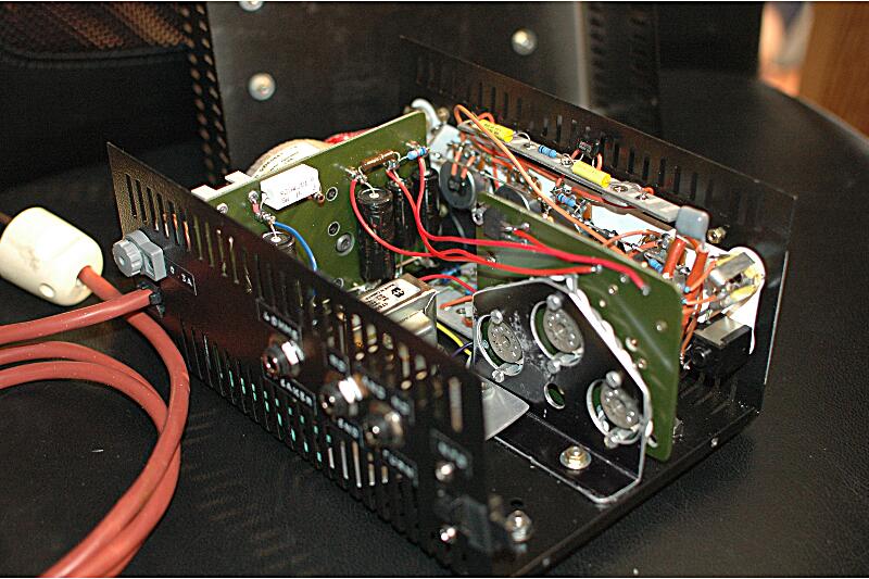
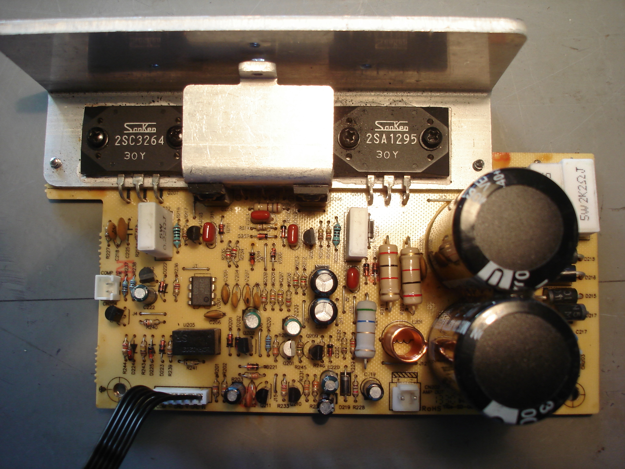
    I've got what looks like a (C5248, A1964) driven push-pull of Sanken (C3264, A1295) chips (plus the board and its power supply) from a cheap - https://www.thomann.de/gb/harley_benton_hbw150.htm - bass amp.

    The amp was not working so I'm not even sure the power section does, but I would have the use of a powerfull SS amp., to plug in the outlet of some tube pre-amp.

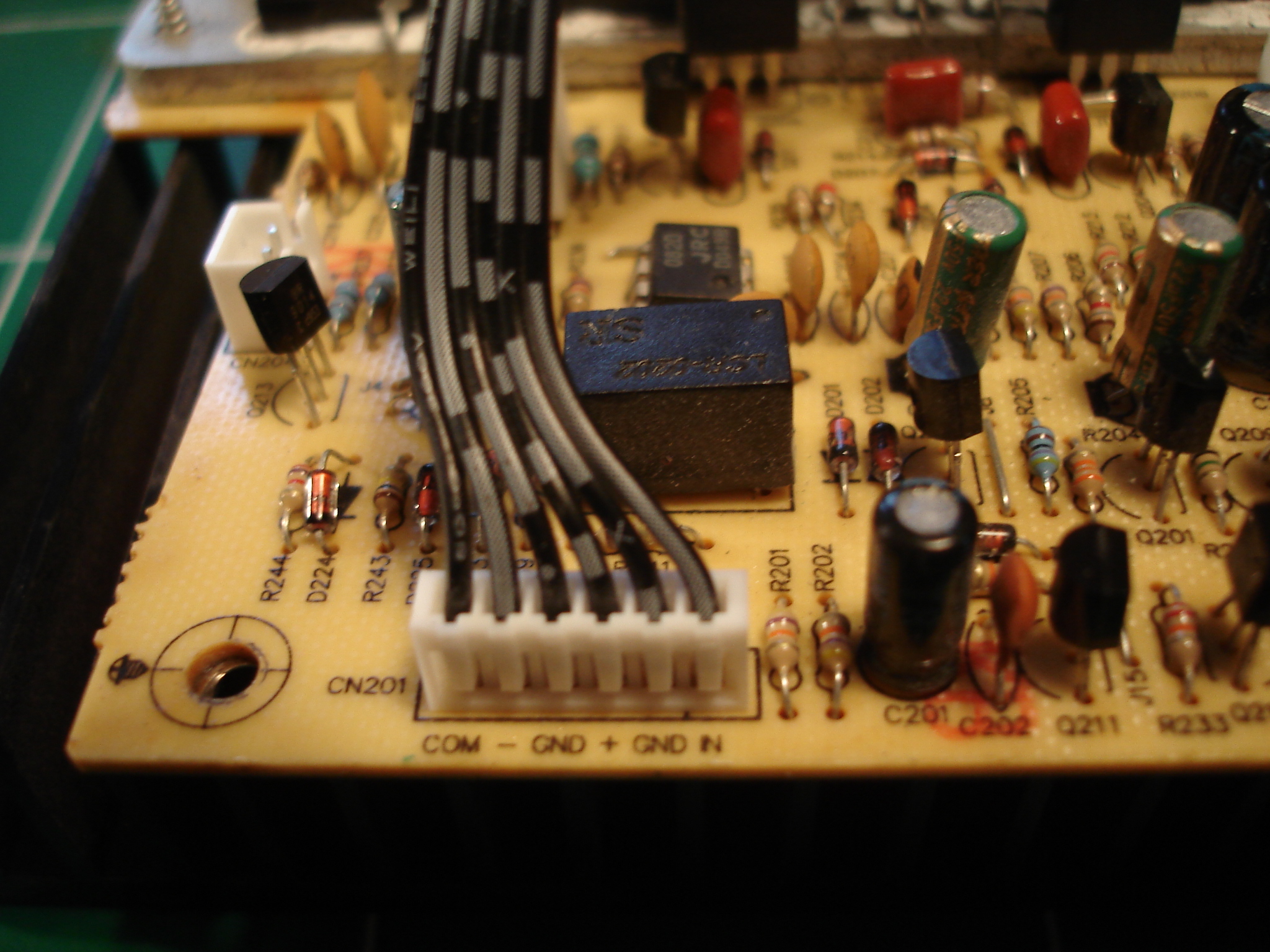
    The board features various annotated plugs so I've got an idea of what (HP, power supply and inboard compressor switch) goes where but the 6 pins input connector, which reads:

    COM - GND + GND IN

    Additionaly the board seems to have some additional gain stages - plus the compressor circuit, so I'm not sure about where to start & I did not find a lot of info elsewhere. I thus look forward to reading any comments, suggestions and criticisms.

    Thanks for your interest, anyway.

  • #2
    Welcome to the forum!

    From a functional standpoint, once you get the amp working again, I see it does have Premap Output/Power Amp input jacks, so you certainly could patch a tube preamp into the Power Amp input jack. Now, if you're looking to build a tube preamp into teh chassis, that's another matter.

    What's your skill level in electronics? Have you done repair work on solid state amps, and have the basic equipment (DMM, signal source, scope, tools)?
    Logic is an organized way of going wrong with confidence

    Comment


    • #3
      First thing I do with a nonfunctional amp (that powers on) is try to isolate preamp from power amp. If you have preamp out / power amp in jacks that makes it pretty easy. Putting a signal into the power amp in is usually easiest. If the power amp is working even plugging a guitar directly into the power amp in should give you some output (although not full volume). For testing preamp I line out from the preamp out jack to a known good amp and speaker combo and see what is working or not working. Once you figure out if pre and power amps are functional you can dive into what isn't working and why.

      Comment


      • #4
        Thanks for all! I was planning something like that, yes.

        Firstly, I only have the board and the transformer, which connects right to the board. It's my bad. I did not kept anything else of that - way too huge for my room - amp. I was just after the speaker & some hardware. For example the chassis was a most thin sheet of mild steel, certainly not something you would use as a tube amp chassis.

        I found back the amp board and thought it could help me prototype tube pre-amps at low cost - plus possibly make for a light, yet powerfull, combo.

        I started tracing the circuit into jschem. However, I am not skilled at this, so this is a lenghty process - especially as the board seem to also embed a few late gain stages.

        So, the board shows no pre-amp plug but the 6 pin connector

        COM - GND + GND IN
        which puzzles me.

        That's why I posted, with the hope that someone would be possibly inspired by some of the above labels.

        NB: I suspect the power board also supplies the electricity for the "pre-amp" board, which had the tone controls and the other plugs. At least the board embeds a power supply unit, so the + and - could be outputs. The IN is rather likely to be the "live" signal, but the COM really bothers me...

        ... in extenso: could the "COM" pin be the signal reference?

        NB2: It looks like the power amp works by altering the "earthing/reference/-" of the loudpseaker, whose + seems to be connected almost right to the PT secondary, so what should I expect as a polarity for the "live" input signal

        Secondly, I am rather surprised I could find neither a schematic for a basic working example of use for this power chips combination, nor any reference for a guitar amp using them - so...

        ... thanks (again) anyway,

        PS: an introduction to myself? A terrible guitarist & a temerarious tech. I did this


        - see: le Chargeur (yet another EF86 AC4 kind of amp) - The Amp Garage & a few other unrelated things.

        Need I use some special equipment to troubleshoot this power amp? I should be able to buy or borrow it.

        Comment


        • #5
          On the 6-pin connector, COM, (-) & (+) are no doubt the V+ & V- power supply connections, with COM being at or close to GND. Having re-read your last post, it may be that these supply connections are the low voltage supplies to run the preamp. You stated the power transformer is directly connected to the power amp board,. I mised that. That being the case, then there won't be direct connections between the collectors of the NPN and PNP power transistors to the (+) and (-) terminals of the connector. You'll have to look. I would look to see if COM is connected to the Center-tap of the power supply windings that runs your power amp board. You haven't yet shown any photos of what you DO have to work with.

          IN is the unbalance signal input to the amp. I'd assume the output from the amp to be elsewhere. You can verify the (-) & (+) connections, but checking to see if the middle terminal of the 2SA1295 is connected to (-), and teh middle terminal of the 2SC3264 is connected to (+). COM and GND cold be the same, or possibly within 10 ohms or so. GND and GND are probably the same connection on the PCB, or are joined together on the PCB.

          COM is the common signal ground to all of the circuits and does finally get to GND at some location. GND is normally the chassis, where the GRN or Grn/Yel wire of the power cord is tied to (Safety Ground).

          NOT having a chassis to start with, this is now a complex project. The photo above being your work, then you have some basic skills that you'll need to turn what You've salvaged into an amp. You will, of course, need an additional power transformer to provide the heater and high voltage supply to run the tube preamp.

          I'd be looking for some non-working amp head that would lend itself to what you're trying to build. Possibly a rack-mount power amp, like a non-working SWR SM400. I have one of those clunkers here in my bone-yard of my shop, shown below.

          Click image for larger version

Name:	SM400 FV.jpg
Views:	1
Size:	174.7 KB
ID:	848306 Click image for larger version

Name:	SM400 RV.jpg
Views:	1
Size:	197.0 KB
ID:	848307 Click image for larger version

Name:	SM400 FTV-inside.jpg
Views:	1
Size:	184.3 KB
ID:	848308 Click image for larger version

Name:	SM400-Insides-PS.jpg
Views:	1
Size:	155.3 KB
ID:	848309

          They use a tube front end, so the power transformer has heater and HV supply taps besides that of the center-tapped winding to run the power amp. Did you keep the heat sink from your power amp circuit, or just removed the PCB and attached power xstrs?
          Last edited by nevetslab; 01-19-2018, 06:16 PM.
          Logic is an organized way of going wrong with confidence

          Comment


          • #6
            Awe-some!

            Now I see what I've been missing, thanks! And yes, I kept the heat sink.

            Thanks for the pics of the SWR SM400, also. They show why the SWR SM400 is (way - on my side of the ocean -) more expensive.

            About any future build, now:

            - yes, the - let's call it BP150, as it reads - board with the transformer should fit into the half of a 19" rack unit. That should leave enough room for a tube-preamp in the same unit - provided I choose to build it in the rack format. This is another story, though, as recycling the BP150 SS amp board is more something of an opportunistic project.

            I'll post pictures and test what you suggested. I hope I'll make it more clear how close to the GND is the COM pin.

            Comment


            • #7
              So here is the whole mess


              with the AC/In connector to the power transformer


              the Amp/out


              and the input connector


              whose COM pin does not seem connected at all with either pin for the (same) GND.

              The COM goes straight to pin 1 of the transistor close to the inboard compressor switch, on the left of the picture - if I remember well.

              To be continued...

              Comment


              • #8
                We're not seeing the photo's. You'll need to post via 'Go Advanced', and check the preview to make sure they are coming up.
                Logic is an organized way of going wrong with confidence

                Comment


                • #9
                  I'm seeing the photos ok.
                  Originally posted by Enzo
                  I have a sign in my shop that says, "Never think up reasons not to check something."


                  Comment


                  • #10
                    Still the pictures don't show?

                    I always preview my messages (cos' I make some many typos... ) & they do show at mine, but the internet server network is so much a mess
                    (so it's possible they don't show at one time in some region.)

                    I'm going to trace the circuit for the COM, if I can find some time to do it.

                    Comment


                    • #11
                      So flip it over and take a photo of the other side of the board, especially around that COM connector.
                      Education is what you're left with after you have forgotten what you have learned.

                      Comment


                      • #12
                        Can you really trace a circuit from just a picture (or two?)

                        Anyway (any help will be appreciated) here it is (click on the image for the full resolution picture)


                        & the component side


                        I will provide detailled pictures for the above posted ones as well - if I can edit my posts afterwards -

                        Comment


                        • #13
                          I can't edit my older posts so I put the picture for the input connector (clickable for details) here:


                          & thank you very much for your interest

                          (I am currently reading one of the last section of Merlin Blencowe's "pre-amp book" where he mentions he used a solid state amp for outputing some of his pre-amps, so this raises even more my interest.)

                          Comment


                          • #14
                            Well, you seem to have a nice and well made power amp there.
                            Please measure the main rails voltage at the big filters, which I estimate around +/- 50 or 55V, given the 63 V rating of main capacitors.
                            I guess that "+" and "-" at the input connectors are +/-15V supplies for the original preamp, IN is Audio Signal In coming from the Preamp and COM means "common"=Ground.

                            You will need to add an extra transformer to feed preamp tubes filaments and High Voltage.
                            You *might* have a "flying rails" Power amp, where what "should" be speaker out is grounded and "Speaker out" is actually the centerpoint at the Power Supply, but, who cares?
                            You must certainly have a "speaker out connector" on that board.
                            Just plug the proper connector there and wire it to a couple **plastic insulated** (Cliff type) speaker out jacks and plug your speaker(s) there.
                            Speaker does not know or care about where does the voltage across its terminals come from and all you care is that you feed audio to power amp IN and loud sound comes through the speakers.
                            Period, treat it as a "black box" which does what you want.

                            Mount and test the power amp by feeding it audio from an MP3 player or similar.
                            It won´t be loud because such signal is feeble but all we wantb to test is that it works.

                            Only still remaining doubt is checking whether it´s a floating rails amplifier or not, I´m not sure where that idea came from, not impossible but unlikely.
                            The PCB bottom shows a big nice coin sized star ground, so I would ground *that* to chassis and consider it also the Preamp and signal ground.
                            Juan Manuel Fahey

                            Comment


                            • #15
                              Actually, in this case, I think COM means something else. I could be wrong too. There are also GND pins on that connector. I can see from the new photos that the COM pin on the end goes to R244 on the end there, and through that to a leg of the small transistor, the base I think. (Q213?) Nearby connector CN204 in labelled COMP SW - compressor switch maybe? Or less confidently compensator switch. SOmething else?
                              Education is what you're left with after you have forgotten what you have learned.

                              Comment

                              Working...
                              X