 Tweet
Tweet
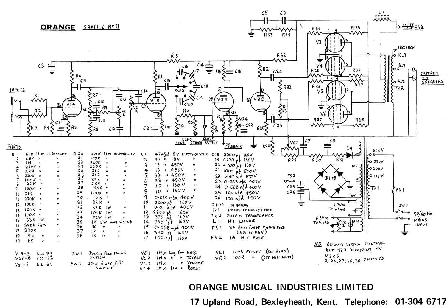
I've been thinking about another build, and I love my old Orange amp, but it's way too loud! I'm ignorant to the world of PI design (and design in general, as I've only cloned). Can anyone point me in the right direction to re-design this split load driver to drive a pair of EL-84s (I'm leaning towards fixed bias)?
They used a few different versions, so whatever might be the best starting point to alter:
http://www.orangefieldguide.com/OFG_...hem_post74.jpg
http://www.orangefieldguide.com/OFG_...20schem_72.gif
I'm looking at cannibalizing an Orange OR-15, for the chassis and transformers, and just popping a turret board in there.
http://i1291.photobucket.com/albums/...psusartvfq.png
PT secondary looks to be good for 250V, or 320V loaded after the rectifier. I'd like to get the pre-amp to run off the voltages the big OR-120 runs off, for it to be as close as possible to an OR-120 with 2 x EL-84 (fixed bias, NFB intact).
Pre-amp voltages at the plates should be something like (According to schematic, I haven't measured in my OR-120 yet):
PI - 275V
3rd stage - 275V
2nd stage - 170V
1st stage - 170V
Thanks in advance for any assistance!
-Nick

Comment