 Tweet
Tweet
i've posted questions and posted references to my plans for this build so i thought i'd post some progress pics and a bit of a description.
there are 3 parts of the chassis'. one for the preamp, one for the transformers, output tubes and PI and the last one for the power supply caps and some controls. the second 2 would have been a single one had i been able to find one large enough, but i couldnt.
there are 2 torroidial power transformers. one for the plate supply, and one for the grids and the preamp. the output transformer is a hammond 1650W, a very big and heavy output transformer, should be up to the job.
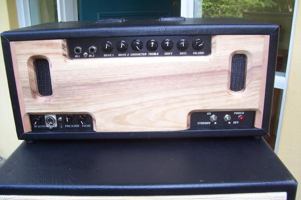
the preamp has a 12ax7 and a 6bl8 triode/pentode tube. the controls are gain 1, gain2, tight, bass, shift (shifts the adjustment points of the james tone stack) treble and volume. the 2 channels are parrallel triode gain stages with slightly different operating conditions. they can be bridged by the switch below them. there are also controls on the bottom chassis which are a presence and focus control. they just alter the feedback loop. the presence control is something i thought of that allows reducing and increasing the feedback for the high frequencies, as opposed to just reducing. i'm not sure how well it will work out, but i will see. there is also a balance DI output that is drawn from the output of the amp which is what the XLR connector is for. the pot next to it is the level control.
the phase inverter uses a 12ax7 followed by cathode follower for each side of the signal from a 12at7.
the output tubes are set up fairly traditionally. there are bias settings for each pair of output tubes and there are bias points that are available to be tested on the rear of the amp (will be hidden behind the rear panel incase someone likes playing with screwdrivers). there are also fuses on the cathodes of each pair of output tubes. this should allow the amp to keep running when a tube goes bad instead of blowing the main fuse and causing alot of confusion. there is also a fuse for the secondaries (tied to a shared ground for the plate and grids supply), a fuse for the grid's/preamp supply and of course one for the mains connection.
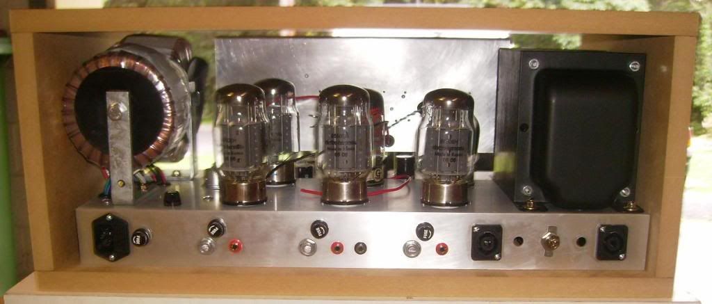
the head case is going to be covered with black vinyl/tolex type material, but i will have timber front and rear panels. there will be cutouts for the controls and possibly ventilation on the front panel, and the rear panel will allow ventillation and will have 2 small fans attached to it. the timber for the visible panels is victorian blackwood (australian timber). the pieces can be seen in the images.
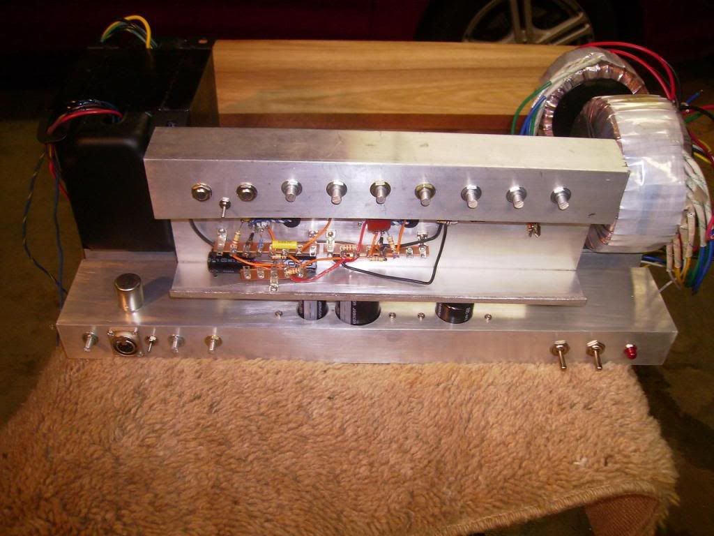
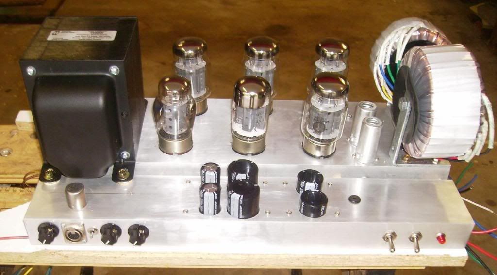
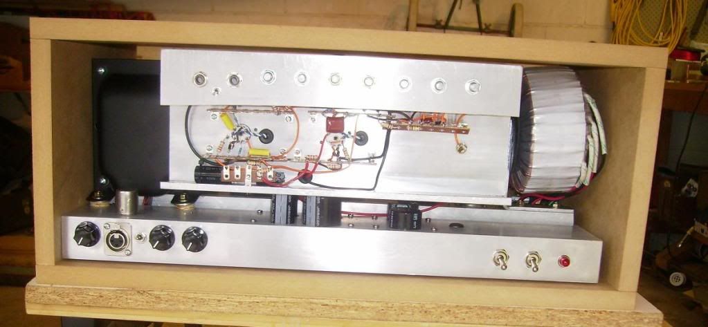
the above photo shows essentially how the chassis' fit together. the preamp chassis is connected to the front panel around 15mm higher than it currently is. the output transformer has its feet pointed down (i put it upside down so i didnt rest 13kg on the leads coming out)
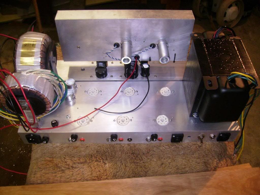
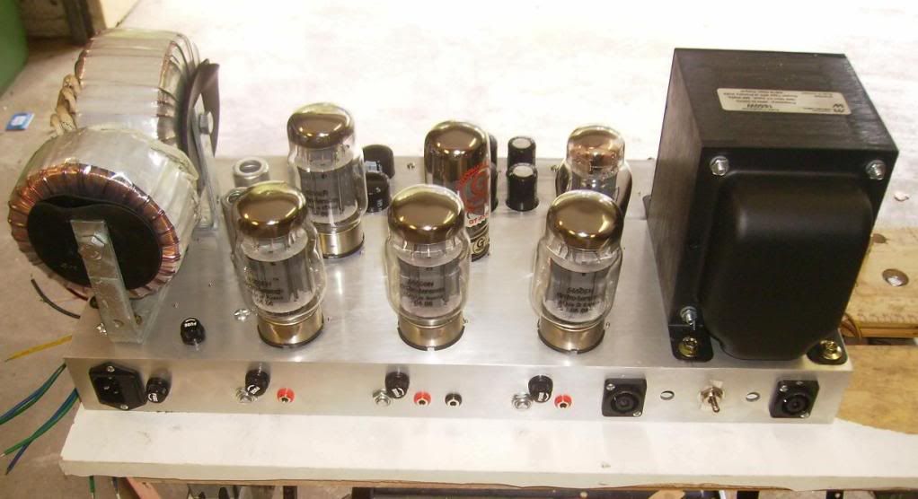
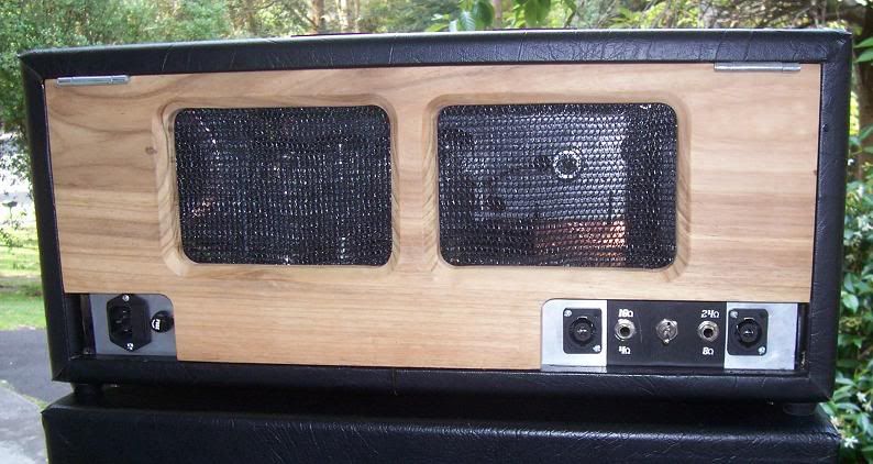
this is the rear view of the bits together. i needed to have the filament connections come out of the preamp chassis anyway so i dicided to have each one go into the chassis just next to the tubes to avoid having them near much of the circuiry. guess its a form of shielding ignore the many leads floating around from the transformer and such..
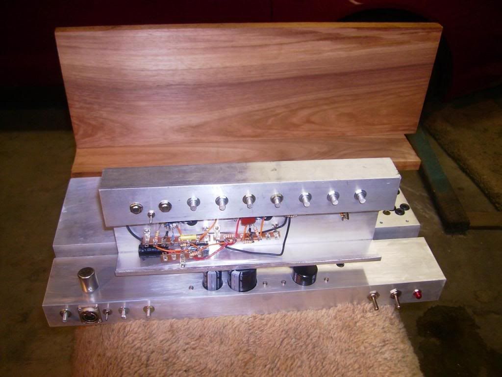
this shows the blackwood panel that will be on the front and the rear of the amp.
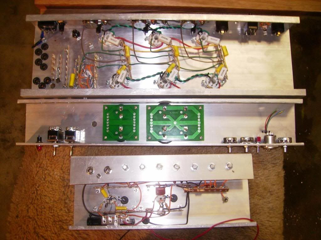
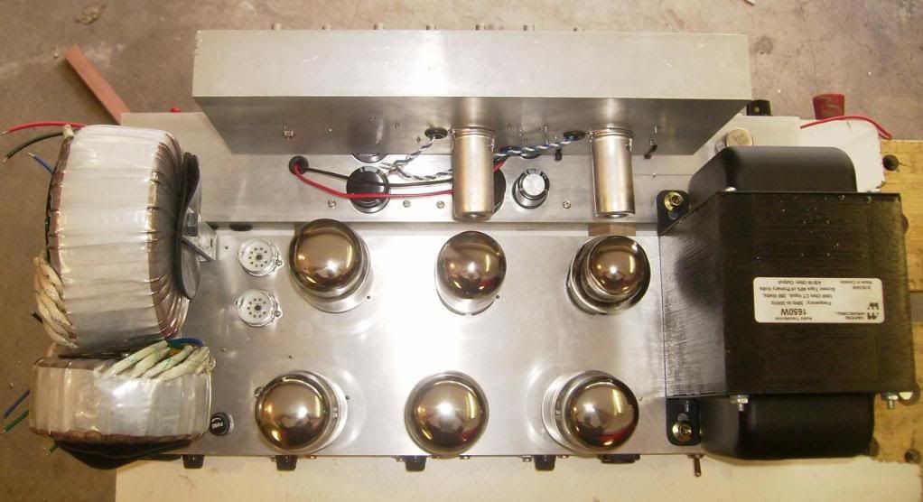
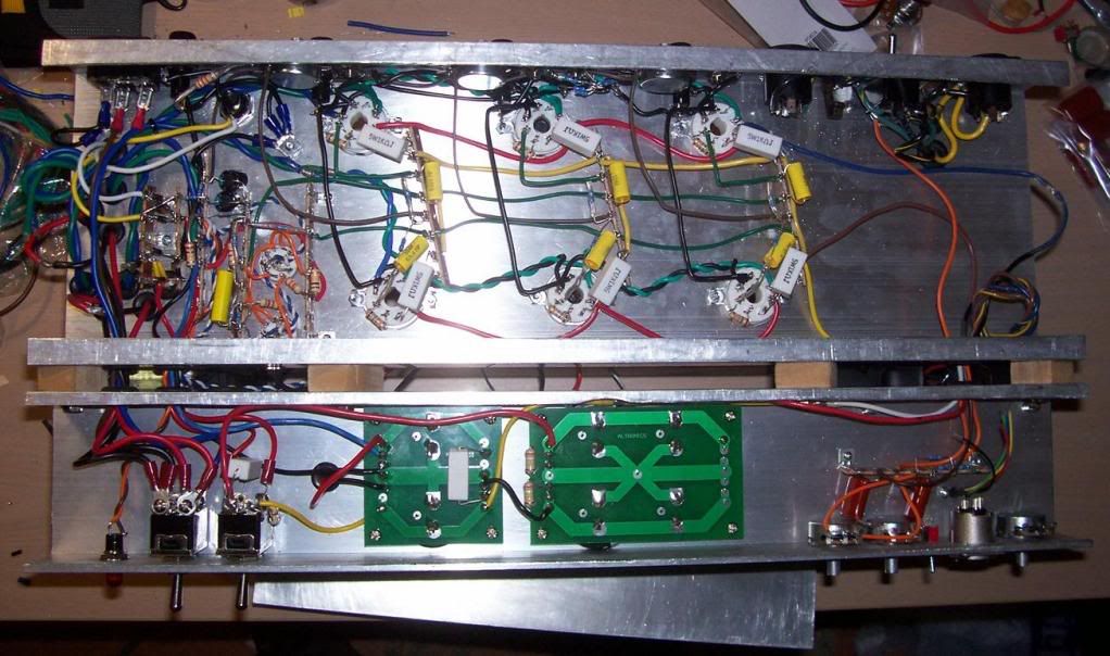
this shows the circuitry thus far. the preamp is done aside from connecting the ground, filaments and B+ leads. the power supply caps are mounted on some boards i got at an electronic shop for power supplies which work quite well to mount them and for their circuitry. the power board is around 3/4 finished. the PI is finished (but i need to move the input jack), the output tubes are mostly finished (just need to connect the cathodes to the bias test points and set those up). i need to do the rectifiers and the bias supply and connect the transformer leads to the circuit. the output transformer requires more complicated impedance switching controls so i am using a switch and 2 separate connections to allow 4, 8, 16 and i think 24 ohm impedance taps. this still needs to be wired up.
there are 3 parts of the chassis'. one for the preamp, one for the transformers, output tubes and PI and the last one for the power supply caps and some controls. the second 2 would have been a single one had i been able to find one large enough, but i couldnt.
there are 2 torroidial power transformers. one for the plate supply, and one for the grids and the preamp. the output transformer is a hammond 1650W, a very big and heavy output transformer, should be up to the job.
the preamp has a 12ax7 and a 6bl8 triode/pentode tube. the controls are gain 1, gain2, tight, bass, shift (shifts the adjustment points of the james tone stack) treble and volume. the 2 channels are parrallel triode gain stages with slightly different operating conditions. they can be bridged by the switch below them. there are also controls on the bottom chassis which are a presence and focus control. they just alter the feedback loop. the presence control is something i thought of that allows reducing and increasing the feedback for the high frequencies, as opposed to just reducing. i'm not sure how well it will work out, but i will see. there is also a balance DI output that is drawn from the output of the amp which is what the XLR connector is for. the pot next to it is the level control.
the phase inverter uses a 12ax7 followed by cathode follower for each side of the signal from a 12at7.
the output tubes are set up fairly traditionally. there are bias settings for each pair of output tubes and there are bias points that are available to be tested on the rear of the amp (will be hidden behind the rear panel incase someone likes playing with screwdrivers). there are also fuses on the cathodes of each pair of output tubes. this should allow the amp to keep running when a tube goes bad instead of blowing the main fuse and causing alot of confusion. there is also a fuse for the secondaries (tied to a shared ground for the plate and grids supply), a fuse for the grid's/preamp supply and of course one for the mains connection.
the head case is going to be covered with black vinyl/tolex type material, but i will have timber front and rear panels. there will be cutouts for the controls and possibly ventilation on the front panel, and the rear panel will allow ventillation and will have 2 small fans attached to it. the timber for the visible panels is victorian blackwood (australian timber). the pieces can be seen in the images.
the above photo shows essentially how the chassis' fit together. the preamp chassis is connected to the front panel around 15mm higher than it currently is. the output transformer has its feet pointed down (i put it upside down so i didnt rest 13kg on the leads coming out)
this is the rear view of the bits together. i needed to have the filament connections come out of the preamp chassis anyway so i dicided to have each one go into the chassis just next to the tubes to avoid having them near much of the circuiry. guess its a form of shielding ignore the many leads floating around from the transformer and such..
this shows the blackwood panel that will be on the front and the rear of the amp.
this shows the circuitry thus far. the preamp is done aside from connecting the ground, filaments and B+ leads. the power supply caps are mounted on some boards i got at an electronic shop for power supplies which work quite well to mount them and for their circuitry. the power board is around 3/4 finished. the PI is finished (but i need to move the input jack), the output tubes are mostly finished (just need to connect the cathodes to the bias test points and set those up). i need to do the rectifiers and the bias supply and connect the transformer leads to the circuit. the output transformer requires more complicated impedance switching controls so i am using a switch and 2 separate connections to allow 4, 8, 16 and i think 24 ohm impedance taps. this still needs to be wired up.

Comment