Announcement

Collapse
No announcement yet.

5F1 - hum and speaker crackle

Collapse
X
 
  • Filter
  • Time
  • Show
Clear All
new posts

  • 5F1 - hum and speaker crackle

    New member here.

    Just finished a new 5F1 amp ($300USD in parts) and I'm not really impressed with results regarding hum. The sound of my guitar thru the amp was very good for a day or so and now a crackle from the speaker when playing guitar at 1/2 to full volume. I expected lower noise from this amp (little or no hum) . Of course, when you hear the guitar playing thu the amp it cancels out the hum, but not the new crackle, gets worse with volume level. Is it normal for the amp to have a certain amount hum like this ? I know the crackle sound is not normal.

    I've read thru a lot of 5F1 posts here and tried to apply different
    solutions to lower the hum level with no real amazing results. I'm not new to building electronics gear, but this is my first tube amp build. I do understand good grounding techniques, but this build is particularly challenging.

    This 5F1 looked to be an easy build, maybe not.

    The amp has a incremental hum as the volume increases. not sure if this is normal
    with a 5F1 champ. Tried two filament arrangements below. I have not tried the 100 ohm resistor
    trick with a sudo center tap since I do not know how it is implemented - need a schematic to
    understand it.

    1. filament wires one grounded with HT center tap to chassis next to the PT transformer and the other soldered to pin 7 6v6 and 4-5 12ax7. Pin 1-2 6v6 and pin 9 12ax7 grounded to chassis nearest the tube socket. Pilot light receives one ground and one hot filament wire from PT transformer.

    2. 2 Filaments wires (floating) directly to Pilot then to 6v6 (pins 7, 1-2) then to pin 9 and 4-5 of 12ax7. Wired away from other signal wires and tightly twisted to meet each tube socket.

    If I compare the two, the floating filament arrangement has a hum and a buz.
    the non-floating arrangement found on original Fender layout has a hum but
    no buz. The hum increases as the volume knob is turned up. The floating arrangement has proven to be the worst with noise. moving the floating twisted wires around makes no difference in buz or hum.

    a new problem occured when I turn the amp volume up and play a open bass
    string (6) on a normal guitar, not bass guitar, the speaker has a horrible crackle in it. I connected another new speaker to the amp and it crackles as well. It's not a bad speaker, must be in the amp. Speaker polarity connection observed (+/-). The Speaker is a Jensen P8R alnico. The crackle was not evident the first day playing thru the amp , but its there now. Not sure why or how. What would cause this ? double checked all the components in the amp. is speaker coil fried ?

    When I initially completed the amp I had a squeel which was solved by correcting the wire arrangement on the OT transformer. Just switched the secondary connections and fixed it. At this time there was no crackle sound coming from the amp. Actually sounded good except for presence of the hum which is still present.


    Here are particulars and voltages associated with this 5F1 build.

    Metal chassis nickel plated , cut outs, transformer orientation and component arragement very similar to
    original Fender layout and metal box design.

    New Sensor PT NSC125P1B
    Primary - Black , Black
    Secondary - red, red-yel/CT, Red 650V/CT @70ma
    grn, grn 6.3v @2a
    yel, yel 5v @2a

    Hammond 125C OT - has selectable primary and secondary impedances.
    primary blue, red/ct, brwn ( red wire center tap not used ) 6400 ohm primary impedance selected.
    secondary (4, 6 tap) 4 ohm secondary selected

    Jensen Alnico P8R , 4 ohm

    Measured Voltages

    Line voltage 122 vac ( a bit high )

    40ma bias set on 6v6 using 1 ohm resistor in line before 450 ohm 5W and 200 ohm 2W adjustable pot. Allows
    bias adjustment on 6v6 tube from 35ma to 45ma.

    Heater Voltage set to 6.04 VAC ( 1 ohm 2W resistor in line with one filament wire ) resistor used to bring voltage down from 6.9 vac , due to elevated line voltage

    6V6- voltages
    pin 3, 402vdc
    pin 4, 363vdc
    pin 8, 20.62vdc

    12ax7- voltages
    pin 1, 216vdc
    pin 6, 211vdc
    pin 3, 1.45vdc
    pin 8, 1.27vdc

    5y3 - voltages
    pin 4-6, 351vac on each leg ( approx 700 vac, should be 650 vac) a bit high , may need a dropping resistor here.
    pin 2-8, 5.3vac
    pin 8 to first filter cap 16uf/475 cap is 409 vdc


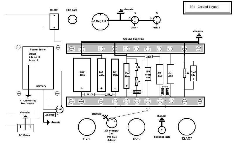
    Links to chassis layout images
    http://img.photobucket.com/albums/v6...wall/5F1_2.jpg

    http://img.photobucket.com/albums/v6...wall/5F1_3.jpg

    http://img.photobucket.com/albums/v6...wall/5F1_4.jpg

    http://img.photobucket.com/albums/v6...wall/5F1_5.jpg

    All tubes tested with Hickok 600A tester prior to initial power up.
    tube sets include one NOS set , and one new Sovtek set. no differences
    heard between the two with hum levels. Using ceramic tube sockets on chassis.

    All components tested with cap checkers and all resistors check for resistance
    before and after completion of the build. All components chosen within 5% tolerance of original.
    resistors are carbon composition. bias resistors are wire wound.

    components connected and soldered using x2 terminal blocks rather than turret board. Ground bus wire connecting all components exactly in original fender layout and grounded to chassis. chassis is being used
    as star grounding point. All grounding points are .1 ohm and less to each other.

    15uf/50V cap across the 1.5K 1/2W resistor connected to 12ax7 pin 3.
    1.5 vdc measured across the resistor.

    seperate clarostat sealed volume pot and on/off switch. pot grounded to
    input jacks. jacks grouned to chassis.

    Shielded wire to volume pot center tap from 12ax7 pin 7 , shield connected to input jack ground. input jack grounded to chassis.

    measured all electrolytic caps for shorts to ground , no issues.


    Why does my speaker crackle and can I reduce hum noise level ?
    any help from veteran amp builders would be great.
    Last edited by electrochronic; 11-26-2009, 04:16 PM.

  • #2
    As far as ground goes, you've made quite a few mistakes. But, first things first. Do you get hum through the speaker with the 5Y3 removed from the amp? If so, you will have to move or rotate the output transformer. Try to find a location where any hum is minimized and bolt it down.

    Next, remove the cap from one side of the fuse to ground. That's the "Death Cap". It's not needed with a three wire line cord.

    The bias pot... does it get very hot? It looks like a 1/2W pot. You really need something more heavy duty there. It could be causing the crackle. I'd measure the resistance and replace it with a fixed resistor. While you are at it, move the ground connection to the minus side of the 16uF cap. Also move the HV CT to the minus side of that cap.

    Remove the ground from one side of the heater supply. Make sure there is no connection to ground at either tube or the pilot light. Twist the heater wires from the transformer and connect them to the pilot light. Run a twisted pair from the pilot light to the 6V6 and 12AX7. On the 6V6 socket connect a 100 ohm 1/2W resistor from pin 2 to pin 8. Also connect another 100 ohm 1/2W resistor from pin 7 to pin 8.

    That should get rid of a large percentage of the hum. Report back and we'll go to work on the rest of the ground issues. Still have the crackle? Does it crackle with the volume control all the way down? Does the volume control affect the crackle? Does it crackle if you smack the amp? Does it crackle with the 12AX7 removed?
    WARNING! Musical Instrument amplifiers contain lethal voltages and can retain them even when unplugged. Refer service to qualified personnel.
    REMEMBER: Everybody knows that smokin' ain't allowed in school !

    Comment


    • #3
      LoudThud,

      Thanks for reading thru this mess. I will try your suggestions out and report back. I'm sure this can't be to complicated, just blindsided at the this point.

      I know I'm jumping ahead on this question but , I'm finding that with the line voltage I get the following voltages with various PT's with in circuit measurements.

      650vct yields 351-0-351 vac (~700vac )
      540vct " 305-0-305 vac (~610vac )
      6.3 " 6.9 -7 vac
      5.0 " 5.6 vac

      This has to be bad for tube life if anything.

      should I consider this build get a lower HT PT to knock voltages down a bit ?
      410-450 vdc on a 6v6 plate seems extreme when 360 vdc is max according to GE /RCA NOS tube specs.
      Last edited by electrochronic; 11-29-2009, 09:49 PM.

      Comment


      • #4
        Originally posted by electrochronic View Post
        LoudThud,
        I know I'm jumping ahead on this question but , I'm finding that with the line voltage I get the following voltages with various PT's with in circuit measurements.

        650vct yields 351-0-351 vac (~700vac )
        540vct " 305-0-305 vac (~610vac )
        6.3 " 6.9 -7 vac
        5.0 " 5.6 vac

        This has to be bad for tube life if anything.

        should I consider this build get a lower HT PT to knock voltages down a bit ?
        If your 650VAC HT winding is centre-tapped and it measures 351-0-351VAC, are you measuring it with the PT unloaded? (By rights you should get 325-0-325VAC when it is loaded, which will rectify to about 360VDC B+ with a 5Y3G rectifier (again - when all the tubes are plugged in).
        Building a better world (one tube amp at a time)

        "I have never had to invoke a formula to fight oscillation in a guitar amp."- Enzo

        Comment


        • #5
          Tubeswell,

          That 351-0-351 (~700 vac) was measured in circuit loaded with all tubes installed. The transformer is a Newsensor NSC125P1B rated at 650 VCT or 325-0-325 70ma. The output on the 5Y3 pin 8 was between 410 and 450 Vdc depending on which rectifier tube I chose to use.


          I agree it should be 325-0-325 , but its much higher and this might be due to my line voltage.
          Last edited by electrochronic; 12-01-2009, 06:42 AM.

          Comment


          • #6
            Sounds like you've forgotten to solder (or poorly soldered) a joint somewhere, and it's becoming intermittent.

            You can try to track it down with the chopstick test (poke wires and components with a chopstick while the amp is running, the offending part will crackle when you prod it)

            Or you can just go back and resolder every joint in the amp, shouldn't take too long in a 5F1.

            If it doesn't respond to the above, then it's most likely a faulty tube or component.

            The heater circuit should not be left completely floating. Either ground the centre tap of the heater winding, or elevate it with a positive DC voltage, which has to be bypassed to ground with a capacitor.
            "Enzo, I see that you replied parasitic oscillations. Is that a hypothesis? Or is that your amazing metal band I should check out?"

            Comment


            • #7
              Firstly, your voltages are not particularly high (if you had 420-430v WITH A 470ohm CATHODE RESISTOR that may be an issue, even then you would normally just rebias), no dropping resistor needed after the rectifier, no dropping resistors required in the heater circuit. Your filament dropping resistor is way under rated, that 2W resistor will burn up...take it out you don't need it anyway (anything up to 7VAC is OK).

              As Loudthud says, you may as well eliminate the bias adjust pot, use a fixed resistor of 470 or 680ohms.

              If you have any kind of hum, why do you still only have a 16uf main filter cap? Fender used small filters because they were cheap & the champ was a low budget amp...use 40-50uf instead (I'd use 100uf personally).

              Your chassis is small, even for a champ. You could probably wire that coupling cap from V1 pin 6 direct to the power tube socket, replace & ground the 220K 6V6 grid load resistor to a solder tag under the 6V6 socket nut, or to main B+ ground (whichever gives least noise).

              Ground main & screen supply filters to the same point as the PT B+ centre tap (PT bolt), not on the preamp buss.

              Can you double check the cathode resistor values at V1 pins 3 & 8, voltages look OK-ish but colour bands don't seem to match with 1500ohms (Brn/grn/red)?

              Comment


              • #8
                Thanks for the new replies

                MJWB,
                I undertand the circuit is unregulated, but do you think a 6.9 vac heater supply is shortening to heater life ?
                6.9V is what I measure under load without the dropping resistor. I really dislike the use of dropping resistors especially on the HT and currently I do not have one in for the HT, but how to correct for overvoltages on the heaters ?

                I have the amp gutted and am trying each suggestion in successive
                steps to see where each one makes the difference.

                I have mounted the OT transformer so I can easily move and mount it
                to avoid hum from the PT. Currently it is re-positioned further away from the
                PT at a right angle as a starting point. Further adjustments may be necessary.

                Some resistor values ( incorrect colors ) were chosen because they
                measured on ohmmeter to within 2% of original bluprint values. This
                means they could be as much as 10% or more out of their original
                color coded values. Not sure if this is a bad approach or not. If they
                are measured good on a ohmmeter correctly does this mean their ok
                or does this mean their unuseable, drifty or unreliable under power ?
                It does'nt seem to effect my voltages adversely.

                The ground reference on this is build is puzzling. I would imagine once I establish a star point on a clean steel nickel plated chassis using solder tags or whatnot, it seems all grounds preamp or otherwise would also use it. If one ground is established at the IEC pin3, PT, CT and #1 filter cap and another on the opposite end of the chassis for the preamp , dont they both share a common ground ? If not , explain ? Just curious

                As Loudthud suggested , I removed the Bias pot and now have a 500ohm 5W in place as a starting point. I kept the 1 ohm 3 watt before the Bias resistor to use a point to monitor and convert millivolt measurements directly to milliamps of bias current for the 6V6.

                I'm not yet at the point to fire this up yet, still on the soldering bench
                Last edited by electrochronic; 12-02-2009, 05:32 PM.

                Comment


                • #9
                  You'll get hum if you ground the hi current power amp grounds to the same point as the low current preamp grounds.

                  PT CT, main B+ filter cap & screen supply filter cap, power tube cathode resistor & 220K grid load resistor all go to a ground at the PT end of the amp (though you might get away with grounding the 220K at the tube socket?), seperate wires for each component (don't string them all together).

                  Input jacks, vol pot, preamp cathodes go to input jack #1 ground. V1 pin 3 cathode resistor & cap can share a wire, but pin 8 resistor can have it's own wire.

                  All grounds meet up eventually through the chassis, you just don't want hi & low current sharing the same wires to the ground point.

                  On every hum free amp I have seen the power cord/IEC has it's own ground at it's own PT bolt...to be honest it may be just more convenient like that, I have never tried it any other way.

                  Befrore I get bombarded with posts saying Fender never did it that way (which is correct, they didn't) remember that they had a proven layout & full time test shop, a little hum wouldn't have bothered them...especially if it was going to rack up $/hours on an entry level amp.

                  Fender used 10% tolerance resistors, so if your "22K" resistor reads 30K it's probably getting burned & may be on it's way out. However if you like the sound of 30K then fit a new 30K part.

                  Comment


                  • #10
                    Here's a schematic I modified to show how I would connect ground. It shows updated line cord and an elevated heater supply.
                    Attached Files
                    WARNING! Musical Instrument amplifiers contain lethal voltages and can retain them even when unplugged. Refer service to qualified personnel.
                    REMEMBER: Everybody knows that smokin' ain't allowed in school !

                    Comment


                    • #11
                      Originally posted by electrochronic View Post
                      Tubeswell,

                      That 351-0-351 (~700 vac) was measured in circuit loaded with all tubes installed. The transformer is a Newsensor NSC125P1B rated at 650 VCT or 325-0-325 70ma. The output on the 5Y3 pin 8 was between 410 and 450 Vdc depending on which rectifier tube I chose to use.


                      I agree it should be 325-0-325 , but its much higher and this might be due to my line voltage.

                      How high is your line voltage?

                      Did the PT come with alternate primary taps (that you could swap to to lower the voltages)? (Sorry I didn't bother checking out the PT schematic)
                      Building a better world (one tube amp at a time)

                      "I have never had to invoke a formula to fight oscillation in a guitar amp."- Enzo

                      Comment


                      • #12
                        350-0-350VAC is typical for a Champ style PT, what kind of 5Y3 do you have, a NOS tube will drop more voltage than the Russian Reflector/Sovtek variant.

                        Comment


                        • #13
                          Loudthud,

                          studied the updated schematic you posted - thanks.

                          After some bench time, fired up the amp today. Here are the results

                          The Hum is gone, when I turn the volume all the way up it is
                          at very acceptable levels of noise for a tube amp - good improvement so far.

                          Few fixes I did that probably made a big difference are :

                          1.two 100 ohm resistors installed at the 6V6 tube socket (cured most of the buzzing )
                          2. Re-routing of the grounds, my bus ground wire is still in use.
                          3. Re-positioning of the output transformer at a right angle and further away from the PT by 2-3 inches. ( this stops the 60 hz low frequency hum ) I usually have to do this in most of my projects, so nothing new here, just part of the finishing stages.
                          4. I removed the bias pot although is was not running hot. Am using a 1 ohm 3 watt fixed resistor in series with a 500 ohm 5W. The 1 ohm resistor is there for quick bias current checks, measuring millivolts drop across the 1 ohm resistor. I'm getting equivilent 43 milliamps bias current. Which is fine.

                          However, One problem still remains, I still get a nasty overdriven oscillation on nearly any volume except full volume. I originally called it speaker crackle. The oscillation is activated striking most any note, especially a low note on the electric guitar. To break the oscillation I have to excersize the volume pot until it stops. When I put my hand on the string after striking the note does not stop the oscillation , it kinda goes on its own. At first I thought I may have had a bad volume pot , but I replaced it with a brand new one and it makes no difference. At full volume the amp sounds great, but any other volume setting like 3/4 -1/2 really activates it. I swapped in both a 12AU7 and 12AX7 several , and I still get the oscillation but it is much more subtle with a 12AU7.

                          What could be causing this oscillation ?

                          If I can nail this oscillation, the amp will be done. I believe the oscillation is coming from the Preamp tube. I'm really close to finishing this thanks to all the suggestions and help so far.
                          ________________________________________________________ ___
                          MWJB
                          Also , replacing a NOS (RCA Blackplate) tube rectifier 5Y3 does drop the HT down by about
                          ~40 VDC , approx 410 Vdc output. The Sovtek 5Y3 is putting out nearly 450 Vdc.

                          OK then, 350-0-350 is normal for the HT , good to confirm this.


                          Tubeswell
                          Again my Line voltage is ~120 to 122 vac.
                          No additional primary taps on the PT , would be nice though.
                          ________________________________________________________ ___
                          Last edited by electrochronic; 12-04-2009, 07:13 AM.

                          Comment


                          • #14
                            Well, I took a few hours break and then went back to the bench with the
                            amp wondering what could be causing a oscillation or nasty distortion. By the way there is good distortion and bad distortion, this is definitely bad distortion. Strangest thing is the volume pot has some influence on this
                            problem the amp if having.

                            If I had to guess, It would have to be isolated to the 12AX7 tube , I'm pretty sure this is happening in the preamp section, but no way to prove it. Just a hunch.

                            First question I asked myself , Is there any wires longer than they need to be and I found one that I thought might be suspect. This is the wire that runs from pin 2 of the 12AX7 to the two 68K resistors. I have the resistors soldered
                            and suspended on each input jack, then a single wire from pin 2 (12AX7) to the center of the two resistors (34K ohms in parallel) . The wire I used was a shielded one with one side grounded. I removed it and arranged it so a new wire about half in length was fitted. Fired the amp up again and unfortunately the oscillation was still present as with the longer wire. So no go on this idea.

                            I double checked all my wires to make sure everything was connected soldered correctly to each tube socket - all good.

                            Lastly , I double checked all resistors and capacitors with DMM and they all
                            have correct values. Voltages are pretty much the same as listed in my earlier post.

                            I'm out of ideas, but there is something on my checklist I'm missing. otherwise
                            the amp would not oscillate or distort so bad. the speaker distorts so badly it sounds like crap. At low volumes it sounds ok, but the amp does not handle low notes a high volume - creates the oscillation overload.

                            I'd sure like to put a variable line transformer so I can run the amp with a line voltage of 115-117 vac compared to my everyday 120 vac from the wall outlet. Would like to see if it brings the voltages close to what the Fender schem. shows, allowing the HT to sag a little bit.

                            With all the little techincal issues, this little amp is kickin my behind.
                            Last edited by electrochronic; 12-04-2009, 07:08 AM.

                            Comment


                            • #15
                              Forget dropping the B+, even a Fender built champ won't run the voltages on the schem, your chasing a myth.

                              Have you relocated the coupling cap that runs from V1, pin 6 to the 6V6 grid (and the 220K load resistor at the 6V6 end of this cap?

                              Comment

                              Working...
                              X