 Tweet
Tweet
(This is a repost from TB as I don't think enough light was shed on the idea back there)
Alright, the Hohner B2A I bought second-hand a few weeks back proved its worth as far as the tone's concerned - the EMB-HBs really have a monstrous sound. Now it's time to fix the wiring inside for a few reasons:
Since the bass sounds good as it is, I want to keep as much of the original electronics specs as possible.
However - the tone pot is a 25K audio pot with an unknown capacitor on it. I haven't a multimeter to test it with, so I have no idea what it is aside from a mysterious label 1K10 (which would suggest a 1100nF, or a 1.1 uF capacitor). I haven't seen any 25K audio pots around, and the 1.1 uF caps are also confusing as they're usually either 1.0 uF or 1.2 uF, at least according to most shops.
So, my questions are as follows:
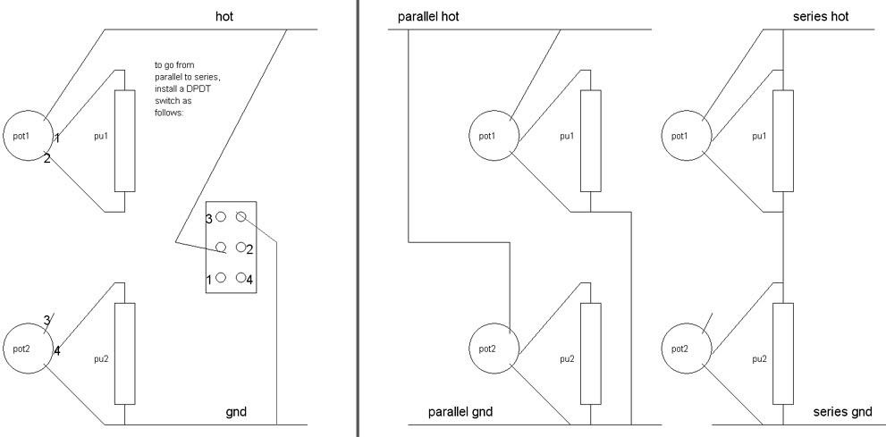
Edit: To clarify on the S/P, this is what I had in mind - snagged the schematic from somewhere at TB.
Alright, the Hohner B2A I bought second-hand a few weeks back proved its worth as far as the tone's concerned - the EMB-HBs really have a monstrous sound. Now it's time to fix the wiring inside for a few reasons:
- The wiring is poorly marked - five out of ten wires are yellow, and the yellow doesn't always designate the ground.
- The pickups are active, thus necessitating a stereo jack.
- The old stereo jack was crackling because it didn't grip the output cable firmly enough - the cable would pop out under its own weight.
- I want to exchange the old three-way switch (neck/series/bridge) with a two-way (series/parallel) complete with the "individual series volumes" mod, pickup loading be damned.
- The red LED has to go - I want a green one.

Since the bass sounds good as it is, I want to keep as much of the original electronics specs as possible.
- The two vol pots are 25K, linear taper - easy to source, makes sense since it's standard value for active pickups.
- The DPDT on-on won't be a bother, and neither will the LED.
- I've already found a decent stereo replacement jack with a chassis mount, as that's the type that fit inside the electronics cavity.
However - the tone pot is a 25K audio pot with an unknown capacitor on it. I haven't a multimeter to test it with, so I have no idea what it is aside from a mysterious label 1K10 (which would suggest a 1100nF, or a 1.1 uF capacitor). I haven't seen any 25K audio pots around, and the 1.1 uF caps are also confusing as they're usually either 1.0 uF or 1.2 uF, at least according to most shops.
So, my questions are as follows:
- Are 1.1 uF caps really available or should I default to 1 uF?
- Could I simply mod a 25K lin pot with an extra resistor to provide the log taper?
- Can someone shed a light on the proper wiring? Or, rather, the proper tone pot and cap values for an active pickup configuration?
- For that matter, can EMGs even be used in series/parallel switching mode? From what I recall the pickup leads are signal +, signal ground, Vcc, -Vcc, shielding GND, so should there really be any issues with an S/P configuration?
Edit: To clarify on the S/P, this is what I had in mind - snagged the schematic from somewhere at TB.

Comment