Announcement

Collapse
No announcement yet.

Badass gremlin

Collapse
X
 
  • Filter
  • Time
  • Show
Clear All
new posts

  • Badass gremlin

    Ok so I have one major gremlin, and Im bamboozled as to what it is:

    Either bright inputs sound ok using vol 1 (middle pot) only; turning up vol 2 to 'mix' in, and big fat 'dead' muffly sound introduced with some buzz too.

    Using normal inputs with vol 2 the dead sound seems stuck firm; turning up vol 1 to mix with, and nothing but buzzy mumbo introduced, getting louder as pot increaces. Using just vol 1 with normals- nothing but this buzz.

    All pot/ board wiring checked 5x- BUT only thing Im not 100% sure is the input wiring: Im using 2 plastic jacks (I hate them as they've 2 pairs of lugs), and 2 metals (2 lugs only) for the lower two nearest board. Ive wired them so: bttm metal jack.. from 'left' on board 68k to its tip, onto placcy jack tip (side that breaks when jack is inserted)- other side of placcy jack tip (side that remains in contact when jack inserted) has board wire from 'right' 68k & the 1m to gnd lug (pairing the sides that remain connected), this gnd lug Ive copper wired to adjacent placcy jack gnd lug and wires from both metal jack's gnd lugs meet it: finally a wire from this to a gnd bolt far rhs--

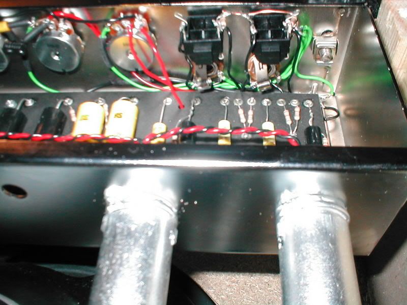
    Ive assumed the 'switch' lug on layouts is the tip lug that is broken (& not gnd lug), and the lower jacks nearest board dont actually need to be these (hateful) switched jack things, and can be as my std 2 luggers.

    Long winded- apologies, I cant explain any other way Im so confused.. http://i102.photobucket.com/albums/m...cture265-1.jpg cheers Captain.
    Last edited by The Captain; 02-09-2007, 07:26 PM.

  • #2
    Captain,
    You may need to get another pair of jacks of the three lug type. The pic I attached is of the 5e3 jack layout, and as you can see the #2 jacks use the "contact point" to ground them when there's no plug in the #1 jack. And when there's only a plug in the #1 jack it goes through both 68k resistors to V1 grid, and 1meg to ground. When none of them has a plug in, the jacks are direct to ground, due to the jack #2 "contact point" going to the "TIP" lug of jack #1, which has it's "contact point" tied directly to ground. When there's a plug in jack #2 only, it's tied to ground through the 68k resistor going to the #1 jack's "tip" lug, which is grounded by jack #1's "contact point". I don't know if the term contact point is the right term, but it is the third lug of a "shorting" type jack.

    FWIW, I use only Switchcraft brand jacks, because they are very high quality, and they make an insulated plastic jack, like the cliff jack, but simpler to use, because they still use the three lug configuration. The number is 112A.
    Check them out http://www.switchcraft.com/products/jack-90.html
    Attached Files
    Sometimes I'm good, then I'm bad..
    http://www.evacuatedelectronics.com

    Comment


    • #3
      Man this is completely foxing me.. thanks for the reply, the answer is there but I cant make sense of it-

      1. is the diagram showing a jack inserted somewhere?
      2. is the 3rd lug of a switching jack breaking contact with the tip or with gnd?
      3. should the pair of metal 2 luggers I have then go as the top pair?
      4. can I use the placcy jacks at all?

      Innitially I had 4 placcys (simple things like metal 3 luggers are rare as hen's teeth here uk), but the space was too tight -right up next to a eyelet on the board. So I thought I had it right that the bttm pair's '3rd lug' was linked to its adjacent gnd lug so the 'switch' bit wasn't effectively being used here, hence my 2 luggers for bttm pair; and spacewise too- the switchcrafts look similarly sized as my rotter plastic bstards.

      Could anyone take a really close-up pic of how the wiring goes? Ive spent so long on this now its just plain daft (I have sportster4eva's pic with his ipod, but cant see which lugs connect to what). Thanks-

      Still bamboozled, Captain.
      Last edited by The Captain; 02-09-2007, 10:17 PM.

      Comment


      • #4
        Cap'n,it sounds to me like you are getting some parasitic introduced at the inputs,but to be honest I find it a bit difficult to decipher your explanation of how you have them wired,it is true,we speak different English on this side of the Atlantic,just kidding,sort of.But let me offer this suggestion,It will help to eliminate any wiring errors here that I cant see and tell us for sure if the oscillation is originating here.I have two 5E3 type amps i wired like this.You really dont need four inputs,so use just 2 inputs and wire them like this.You have a "hot" tip lug,a full time ground lug and the switch lug.Connect your 1meg resistor,from the hot lug to ground,your 68k in series to your input grid wire and the switch lug to ground.Now you should not get the noises you describe.If this doesnt solve the noise problem,then we can try to track them down elsewhere,but I have a strong feeling they are originating here.

        Comment


        • #5
          Right then- Ill give careful thought on that lot from the two replies above and see what happens. I wish they'd made the chassis a bit bigger! terribly crappy description of my gremlins; someday Ill write succinctly I hope.

          Ill report back -great help as usual folks. rgds Captain.

          Comment


          • #6
            I wouldnt say it was a "terribly crappy description",Cap'n.Its not easy to convey what we mean when we are describing noises and tone related issues,you describe it as you hear it,then we have to imagine what it is you are describing,and then we re-describe it and so and so on.It is tough to put in text what is a subjective observation,add to that different terminologies from around the country and the world...what I might use to describe a sound,here in NY, is gonna be totally different from the terminology a guy from the west coast would use.We will always have some degree of miscommunication,I surely meant no offense by my comment on the description,very sorry if it sounded that way.

            Comment


            • #7
              One more thing to watch, that i did.
              The more expensive jacks have the tip as the center lug where the cheeper jacks are the first lug. i followed webers layout and it ended up i wired the jacks wrong. drove me nuts tryin to figure out why i had no sound.
              Joe

              Comment


              • #8
                Ok, after 2 late nights, quite a lot of shouting, swearing and head scratching I think Im there: I second the previous reply as to the weber's input layout: I ditched that (I had used it right up to then), stripped all my inputs out and slowly my brain interpreted the input wiring suggestions above: now all 4 inputs & both vol pots work ('normal' very dark/ muddy, but that I sort of expected reading other's posts) and as far as I can tell it works as it should- great! I even used the wretched plastic jacks too. I plugged in a friends Rickenbacker and it sings well! horrendously loud (neighbours heard it at '1.5' on the vol pot); I didn't manage to get any overdrive (?- Ill cross that bridge later) but hey- gremlins terminated! and its relatively hum-free too. Big thanks again for explanations and help folks.
                Rgds Captain.

                Comment


                • #9
                  Captain

                  Just scroll down slightly on this link to see an excellent description of input jack wiring (not mine!)

                  http://www.hoffmanamps.com/charts/CommonHookups.htm

                  Make sure you use the 4 x Switchcraft 12A (Tip/Switch/Sleeve) inputs.

                  Hope this helps

                  Colin

                  Comment


                  • #10
                    Thanks for that Colin. Why do the Hoffman and the Weber input layouts differ though?

                    1. The hoffman has #1's tip joining #2's switch-- the weber has #2's tip joining #1's switch (which is not connected to the 1M unlike hoffman).. and so..
                    2. The hoffman #1 has the 1M from gnd to tip and one leg joinied to the switch-- the weber #1 has the 1M just from gnd to tip.

                    Which is correct/ why on earth are there two versions?? And can anyone tell me which input #1 or #2 can be used as a std jack, ie non-switching? completely utterly confused (again), thanks Captain.

                    Comment


                    • #11
                      Of all the problems I've had with builders, the improperly wired input switching jack issue has to be one of the top 3 mistakes builders make.

                      With respect the Weber jack layout... there might be another issue because compounding this builders snag is that there is an old WeberVST input jacks parts problem.
                      I can't tell you how many new amp builders have sent me their Weber kits to "fix"... where the switching jacks were totaly screwed up.

                      The "standard" 1/4, switching phone plug jack... for the last +60 years..., has the switching lug in the middle of the other two lugs and the ground lug should be obvious.
                      As viewed from the rear of the "standard jack", with the blade assembly up at 12:00 O'clock and the three lugs down... the right lug is ground (or audio low), the middle lug is the switch, (which, when closed, shorts that lug to the tip lug) and the left lug is the tip lug, or sometimes called audio high.
                      The Chinese parts maker who built those problem jacks for WeberVST must have been on super stupid pills that day and got the lugs on the many of the jacks built wrong.
                      They must have built a bunch of them and had to go ahead with selling/using them.

                      This is just my IMHO but,
                      bogus jacks are simply poison for first time or novice builders.
                      Even though some builders have got them to work fine when wired correctly with respect to their built in lug error, many times the switch doesn't even work once the bushing nut is tightened down.
                      I think they are poorly made and, as far as the novice builder group goes, I advise builders to avoid them.
                      I say just use good Switchcraft jacks or the import ones from MOJO because those jacks are built correctly and the switching blade always seem to work.

                      Since we have no idea which ones you have, you'd have to determine which lugs are which in order to wire the jacks for proper operation.
                      Maybe you need a picture of good jacks, wired correctly, to compare yours to.. not artwork.
                      Bruce

                      Mission Amps
                      Denver, CO. 80022
                      www.missionamps.com
                      303-955-2412

                      Comment


                      • #12
                        Distinguishing which lug is which is straightforward enough (mine are the cheapies, middle lug tip- fine for 3rd price of switchcrafts) & with minimal sense (yes I know its the captain writing!) and looking carefully whichever way one's input lugs are configured even a novice surely cant get that wrong. But my point is there are seemingly two conflicting input wiring layouts, the weber and the hoffman as I elaborated above. Ive used the weber layout (clarity reasons) for the build Im just rejigging my horrid plastic jacks for 'switchcrafts'. Now Colin kindly posted me the hoffman common hookup page- but there is definite almost completely different #1 to #2 configs to the weber (any others too??) causing both gnashing of teeth & the flailing of arms.. again! so until I know what's 'correct' there's no point stuffing them in as its a right b'stard little job as it is.

                        Comment


                        • #13
                          Hi Captain,

                          If you're using the Switchcraft 12A switching jacks (they have Switchcraft stamped into the back of them), then the Hoffman link I sent you is correct.

                          You can get them here...

                          http://rswww.com/cgi-bin/bv/rswww/se...ukie&Nr=avl:uk

                          If you're not, then you'll have to use your multimeter or visually follow the connections around the jack.

                          Colin

                          Comment


                          • #14
                            Im only using copy switchcrafts (2 lugs reversed) so ID is no prob re the tags, or indeed implimenting them to either layout with minimal rejigging. I'll go with your hoffman to start then. Im still wondering which layout Bruce/ Mission or say s2 use (both top drawer makers by the looks of it).. I suspect now the hoffman config, but it'd be helpful/ reassuring to know definitively. Great help folks, Captain.

                            Comment

                            Working...
                            X