Announcement

Collapse
No announcement yet.

Sovtek MIG 60

Collapse
X
 
  • Filter
  • Time
  • Show
Clear All
new posts

  • #31
    Originally posted by Amp Kat View Post
    I think what Max and Enzo are telling you is the zener trick is designed for transformers that have center taps. Yours doesn't have a center tap which is also why it uses full wave bridges instead of just full waves. Another good point that Enzo made is with the lower screen voltage doesn't dissipate as much wattage as at just below plate voltage so I agree with Max that that's what the amp is designed for. I didn't take into consideration of the lower screen voltage so my bad on that but I would leave it as is. The 5199 tube will take the voltage if your worried about that but it's tone IMO is not as good as the EL-34. These amps do sound awesome and are loud as hell so I'd keep it like is. $.002
    I remember the HT on the early MIG 60 we just had in used a bridge rectifier, like you said. In fact the bridge had failed and I built another out of 5408s.
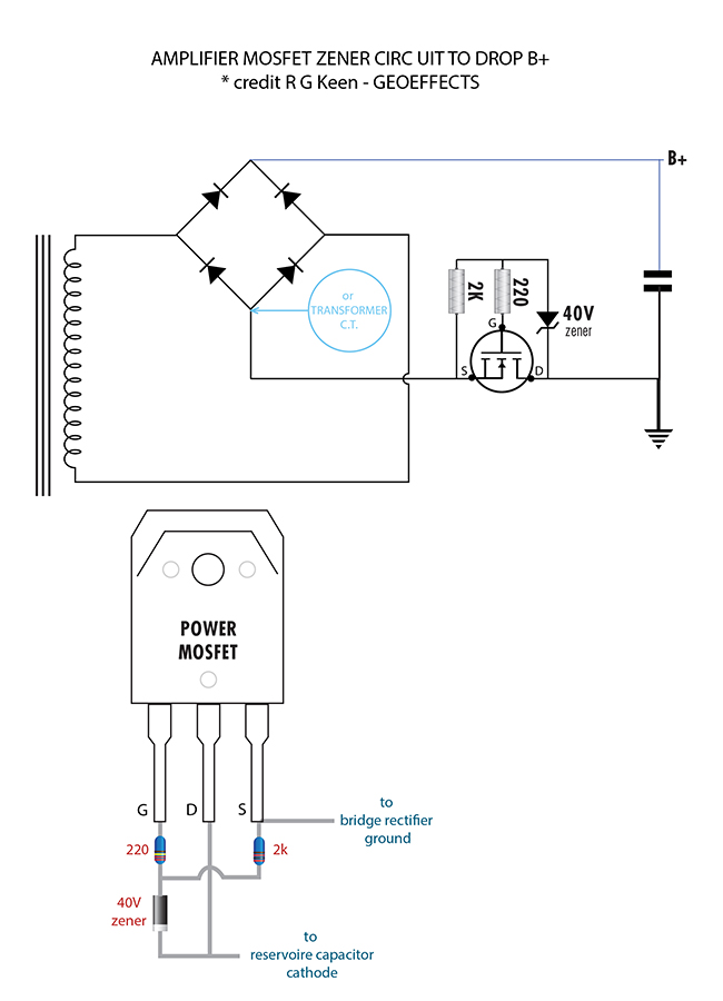
    But you can use a zener to drop the B+ of a bridge rectifier circuit in much of the same way as you would for a 2-phase rectifier. I have a drawing of how to do this using a zener/mosfet combination which was adapted from R.G.'s mosfet follies. I'll track it down and post it....
    (ho)
    If I have a 50% chance of guessing the right answer, I guess wrong 80% of the time.

    Comment


    • #32
      I should add that he came up with a newer (and clever) switching circuit to drop the B+ which I like alot. It looks to be more efficient, but it's a more complicated circuit.

      But here is the older, more common schematic and diagram on how to drop the B+ using a zener/mosfet combo for a Bridge type rectifier. I drew this a few years ago, so if you notice any error, let me know and I'll correct it.

      If I have a 50% chance of guessing the right answer, I guess wrong 80% of the time.

      Comment


      • #33
        Originally posted by SoulFetish View Post
        the calculation for the HT is incorrect. The peak voltage calculation would be taken from the center to one side of the secondary. so if you were reading 210-0-210V RMS, the rectified DC voltage would be calculated 210*1.414=296.94V (under light load).
        Or 420*0.707=296.94V
        That, if it uses a full wave rectifier, which does not seem to be the case.

        A bridge, feeding 2 stacked capacitors and with center tap connected to centerpoint of said stacked capacitors will give you unloaded almost 700V +V
        Juan Manuel Fahey

        Comment


        • #34
          Originally posted by J M Fahey View Post
          That, if it uses a full wave rectifier, which does not seem to be the case.

          A bridge, feeding 2 stacked capacitors and with center tap connected to centerpoint of said stacked capacitors will give you unloaded almost 700V +V
          While it’s much more common to see that configuration to achieve a balanced +/- supply, you’re absolutely correct and I should have specified that. Ill edit the post to clarify
          If I have a 50% chance of guessing the right answer, I guess wrong 80% of the time.

          Comment

          Working...
          X