 Tweet
Tweet
I've got a reverb-related question, if anyone could help me out. I was wondering what the effect of the 3.3M res/10pf cap reverb setup on some Fenders was, in terms of signal drop and tone. I noticed that several used this on the vibrato channel, and then sent the signal through a triode gain stage and mixed it with the normal channel. To my understanding, the two channels weren't used at once...is the second 12AX7 triode just a kind of "transparent" (little to no tone shaping) gain stage to get the levels in the same ballpark? Thanks so much if anyone has time to help me out.
-
-
The large resistor separates the input to the reverb driver stage from the return entry point.
Some amps use the tone stack to do the same thing.
Traynor did this and I think some Ampegs have this feature.
Signal voltage is in the mico amp range so a few volts are dropped.
A recovery stage is a requirement as a result.
The small puff cap acts as a high frequency bypass. Some guys will fiddle with this cap to get some tone change. -
Hey Surfben, I’ve been wondering about this reverb mixing stage myself. Somewhere below is a similar thread I started on subject. I never really got the answers I was looking for though. Here’s what I’ve come up with on the subject using the Twin Reverb AB763 schematic for the examples.
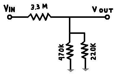
Ignoring the 10pf cap for now, with the reverb turned all the way down, the 3.3M resistor and the 220k & 470k in parallel form a voltage divider which reduces the bypass signal by: Vin * (220k||470k)/(3.3M + (20k||470k)) which is ~ .043Vin or -27db.
My best guess is that this brings the bypass signal down to an appropriate level in relation to the wet signal for mixing. Then the following 12ax7 stage brings this all back up to the level of the normal channel. I forget off the top of my head how to calculate the gain of this stage, but I did it before and I did get something in the + 30db ballpark.
Now what really baffles me is the 10pf cap.
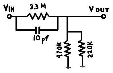
Putting it back in to the equation (pun intended) I calculate the following frequency response for the resulting filter.
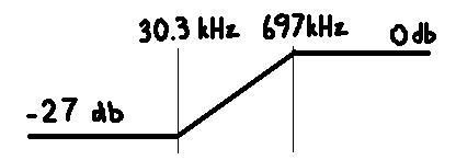
Now what in the blazes is the purpose of bypassing frequencies above 700kHz! I’m obviously missing something. My calculations could be off but I tried it several times.Last edited by Ptron; 06-10-2007, 07:48 PM.Comment
-
I get -3dB of 4.8KHz for 3.3M||10pF.
What am I doing wrong?Comment
-
That would be correct for a regular RC filter
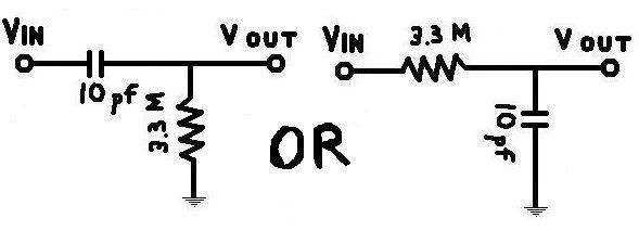
but the frequency response for this configuration will have the shape shown before. Above a certain frequency, the cap is effectively a short and there will be no attenuation. Below a certain frequency, the cap is effectively open and you more or less have a plain �ol voltage divider with the 3.3M and the 220k||470k.
I dusted off my textbook and worked out the transfer function for it.
R1 = 3.3M
R2 = 220k||470k = ~150k
C = 10pf
Zout = R2
Zin = R2 + R1||C
|H| = Vout/Vin = Zout/Zin= R2/( R2 + R1||C ) =...
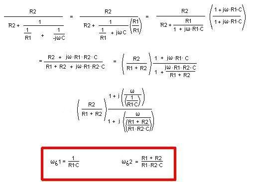
Those two equations at the end give the breakpoints for frequency response. And the R2/(R1 + R2) in the final transfer function equation is the voltage divider ratio that gives us our maximum attenuation.Comment
-
The math is too hard for me to figure out but my ears don't lie.
I can hear the difference with the cap in or out and the speakers used for most guitar amps I mess with are about dead from about 12KHz on.
I can hear quite difference going from no cap to 47pF.
I think the 3m3 resistor makes the 10pF cap "look" large but the "Q" of the parallel RC filter is low.
The 470K resistor is an islolation resistance to keep the reverb pot from loading down the dry signal when the reverb is off.
To me the parallel 220K resistor is more like a grid load resistor that is always in parallel with the 470K isolation resistor so the actual grid load is 150K when the Reverb pot is at zero.
I agree with the voltage 3m3||150K divider thing but the 700KHz high pass just seems way off since I can hear the difference it makes and my old ears are shot from 14KHz on...
I guess I can't see how the divider has much to do with the high (freq) pass since the passing has already happened before the gird load.Comment
-
If you look at just the dry side is there any chance that the 10pf cap is used compensate for Miller capacitance? I realize Zin is much lower that 3.3M, but there is still that series resistance for the dry signal.
Its easy for my ears (probably closer to 10khz) to hear the effects of series resistance. I always figured they wanted to lower the Z at higher frequencies with this reverb mixing technique.Comment
-
It's not that complicated.
As Bruce has posted, at about 4.8Khz the 10 puff's impedance is equal to 3.3M. Thereafter, the relationship changes as you would expect.
It's a frequency dependant bypass filter.
The 470K/220K voltage divider on the output of the reverb stage provides a wet signal to the recovery stage that is roughly 70% attenuated (but then further controlled by a pot).
Remember kirchoffs laws? The current flow (very small) is into the input of the recovery tube, not back through the 3.3M resistor. If that is true, it can have no effect in the voltage divider.Comment
-
Oh for @#$%@'s sake. I just realized what I was doing wrong. My answers are correct...in radians/second! oops. Devide them by 2*pi and you get: 4.8khZ and ~110kHz. so the frequncy response curve is correct just sub in those breakpoints. Sorry 'bout that.Comment
-
It's a pole.
Today, we use it regularly to control gain/frequency characteristics of op amp circuits.
Check out any on-line op amp manual.Comment
-
I'm not sure where this is coming from. I wasn't talking about what happens to the wet signal.Remember kirchoffs laws? The current flow (very small) is into the input of the recovery tube, not back through the 3.3M resistor. If that is true, it can have no effect in the voltage divider.Comment
-
Sorry, I misunderstood.Comment
-
No problem. Sorry I sidetracked this thread because I couldn't rember to convert units (almost said something about keeping my units straight)
So anyway, now I'm wondering, why they shape the frequency response of the dry signal this way. Do the normal channel and reverb channel sound anything alike? (reverb all the way down and all other settings the same) I don't see any corresponding shaping in the normal channel. Seems like any bass roll-off there, due to coupling caps and such, would take place at much lower frequencies. I'm not going to try to calculate it this time guess I'll just have to get my hands on one and experiment.
Comment
-
Next time you have one apart, try no cap vs 47pF... the whole "tone" of the preamp changes and it sounds just a little more gainy too.
I have a Deluxe Reverb here that is in for a tune up... I'll try it too as it has been a long time since I've done it.
I wouldn't be suprised to find out Leo Fender did very very little math and just messed with this tweaking circuit emperically until he found a cap and tone combination that suited him.Comment
-
I'll have to try that this afternoon also because I have a SF DR in too. It's the one with the pull switch boost but should work. You are talking about swapping the 10pf with 47pf right ? This guys says the reverb is too reverby do you think this would calm it down some ? Nice thread btw ! Didn't mean to step on surfbends thread just interested.Last edited by Amp Kat; 06-12-2007, 06:27 PM.KBComment
Comment