Announcement

Collapse
No announcement yet.

Range of bias voltages for power tubes in fixed bias?

Collapse
X
 
  • Filter
  • Time
  • Show
Clear All
new posts

  • #31
    I should probably be less mysterious about this. I'm dreaming up a way to mechanically mount an individual per-tube bias pot on the back of an amp that doesn't require hacking the chassis, just mounting a small (maybe 3" by 3" by 1") box on/under the chassis somewhere. It would let you attach this to an amp easily - if individual per-tube biasing is something you want.

    The idea is to bring out test points for per-tube current measuring from the output tube cathodes and protected access for a screwdriver adjust, while spending some thought about how to make this safe for the amp - for instance, making an accidental probe short not be an amp-changing event.

    This required me to know more than I currently do about the range of voltages and currents in a wider range of amps than I'm personally familiar with.

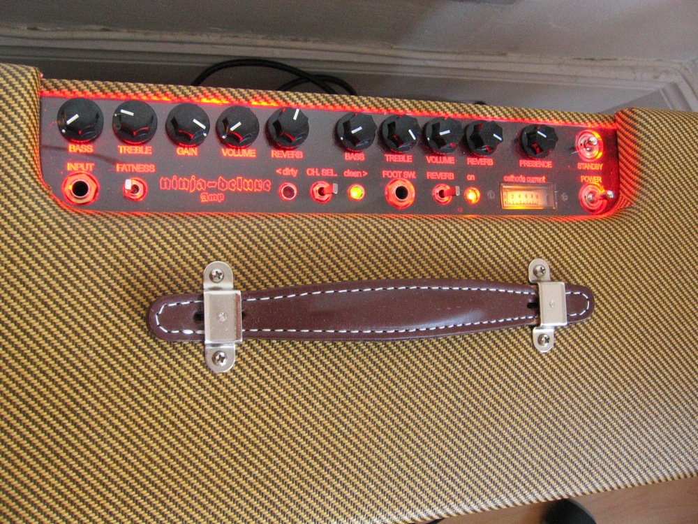
    I've come up with some ideas about how to do this, and while we discuss it here, I've been drawing things. I like my red-light/green-light bias indicator, so I'm also thinking about making this an option if someone wants it. We got really positive reviews on that from everyone we heard from that tried it.

    It's not particularly earth shaking. As the bard said, a small thing, but mine own.
    Amazing!! Who would ever have guessed that someone who villified the evil rich people would begin happily accepting their millions in speaking fees!

    Oh, wait! That sounds familiar, somehow.

    Comment


    • #32
      Whatever the bias voltages normally are, I like them slightly colder for bias-vary trem. (Feel free to factor that in to whatever you're up to R.G.)
      Building a better world (one tube amp at a time)

      "I have never had to invoke a formula to fight oscillation in a guitar amp."- Enzo

      Comment


      • #33
        I was going to ask about asymmetric clipping in that mismatched harp amp. Good point.

        Now that R.G. has let the cat out of the bag, so to speak, I'd like to offer some feedback on a practical application for this type of device. R.G.'s heard all this before as we've been emailing one another for the past week, but I'd like to hear other peoples' thoughts too. Honestly speaking, I think that the amp I'm working on now represents a worst case scenario in terms of needing this sort of solution that R.G.'s thinking about building.

        My application is a 6-tube Fender Super Twin Reverb that I recently obtained as a DOA. It's drive section for the output tubes uses cathode followers to drive three sets of tubes that are bussed-up in parallel. Having been built in the era of "uniform" tubes, bias is set by fixed resistors at -61V and is not adjustable. Well, there is a balance pot. I have to admit that the amp doesn't particularly sound very good. I attribute a large portion of this to the horrible bias arrangement, where the bias is non-adjustable and the amp currently has 6 tubes that are poorly matched. Looking to the future, I can see where an adjustable split-bias system would make long-term maintenance much easier in an amp like this one, so I'm giving it serious consideration. I had already designed a 6-way independent bias circuit of my own when I received an email from R.G. about his microcontroller-based bias box with LED indicators.

        One potential problem that we both noticed immediately is that the real estate in this amp is very cramped, and that there's no room inside of the chassis for an add-on board. This amp already has an extra board in it (compared to the garden variety Twin Reverb) that's used for the 5-band EQ and the ghastly-bad preamp distortion circuit. The result is that things are so crowded that there's no room inside for another board unless you re-work the boards that are already there to free-up some space. There's also no room on the back panel because those 6 tubes and the switching jacks take up a lot of space. We considered that the only mounting option for something like this may be to use an add-on box on the belly of the chassis. Here's a picture of the stock amp:

        Click image for larger version

Name:	str-chassis.jpg
Views:	2
Size:	751.7 KB
ID:	828401

        I really like R.G.'s idea for a bolt-on bias box that would give you independent bias. It looks like it would be pretty straightforward to deploy on an amp that uses single pairs of tubes, but a bit more complicated to use on amps that have multiple pairs of output tubes that are wired up in parallel. To make things work you'd have to de-bus the drive circuits.

        I do like the idea of having externally adjustable bias pots, and LED that work as idiot-lights to help simplify the bias procedure. One potential problem in deploying such a box on this particular amp involves where to locate the box so that it's visible/accessible without removing the chassis. As you can see by viewing this amp from the rear, there's not much room to mount anything on the chassis. All of the chassis space is occupied by 6 tubes, a transformer, or the doghouse. Maybe hanging it off of the doghouse might be an option. If it were something that needed to be mounted directly on the chassis, for this amp, that would mean mounting it toward the front of the amp (behind the doghouse if you're looking at the amp from the rear) which would block line of sight to the LEDs and access to the trimpots. From a practical standpoint R.G., I think if the application would require mounting the box somewhere that the LEDs and trimpots aren't easily accessible, and you have to stick your head into the cabinet or remove the chassis to bias the amp, then there's not a lot of reason not to just pull the chassis and bias the amp on the bench using a meter.

        In a nutshell then, I really like the idea for 6-way adjustable bias. I really like your idea to use LEDs as bias indicators. And I like the ease of use that would come with having everything mounted on a back panel. That would make the package very easy to use for end users. But would it matter to users who are more technically inclined? I don't know. But in this particular application, I'm thinking that I might do just as well to have a small board with trimpots located somewhere inside of the chassis, to pull the chassis and to use a meter with mini-clip leads to grab onto both sides of a cathode resistor.

        Just to reiterate a comment that I made earlier: considering the wide range of bias currents/voltages that would be required for different tube types, if you're interested in building a "universal" microcontroller-based bias circuit, I imagine that you'd need to provide some way for the user to program the controller for different tube applications. I was thinking that DIP switches might be handy in that respect.

        I hope this brings out some helpful ideas from other people reading the thread.
        "Stand back, I'm holding a calculator." - chinrest

        "I happen to have an original 1955 Stratocaster! The neck and body have been replaced with top quality Warmoth parts, I upgraded the hardware and put in custom, hand wound pickups. It's fabulous. There's nothing like that vintage tone or owning an original." - Chuck H

        Comment


        • #34
          Originally posted by bob p View Post
          Just to reiterate a comment that I made earlier: considering the wide range of bias currents/voltages that would be required for different tube types, if you're interested in building a "universal" microcontroller-based bias circuit, I imagine that you'd need to provide some way for the user to program the controller for different tube applications. I was thinking that DIP switches might be handy in that respect.
          I think I have a solution to that. I put in a way to tell the uC to the effect that "this tube is the right current, right now; make your green light for all the tubes be here". So the procedure for setting it up on an amp would be to
          (1) using the measurement points so thoughtfully provided ( ) on the unit, set one tube to the right current by meter and the bias adjuster, ignoring the LED guide for the moment.
          (2) hit the "do it like this" adjuster till the LED turns green
          Done. Now all the tubes' lights go green when their current matches within the few percent error budget. Adjust the other tubes. And as long as you don't care to change that set point, it will always look for that current from each tube.

          @bobp
          I changed to a red-gree-blue LED. Blue = too cold, red = too hot, green is juuuuuuuust right.
          Amazing!! Who would ever have guessed that someone who villified the evil rich people would begin happily accepting their millions in speaking fees!

          Oh, wait! That sounds familiar, somehow.

          Comment


          • #35
            I haven't read every single reply, but I just wanted to mention that a very good practical argument for individual tube bias is not to match hypothetically unmatched 'new' tubes, but rather the ability to replace a single expensive power tube on the road, or maybe use an old spare if that's all you have to get through the next couple of shows.

            Another consideration is that any guitarist who buys a unit like RG is imagining already has some idea of what bias is and what they're getting into. Not every guitarist cares, but even if they have an amp that has user-adjustable bias controls doesn't mean they actually have to use them, and can still take the amp to a tech if they prefer. In theory, any honest tech would charge next to nothing for biasing an otherwise healthy amp using its external bias controls. I mean unless you taking the chassis out of a Fender

            Comment


            • #36
              One situation I can imagine is that just before or during a gig, either one dies or the amp just gets ugly. You can actually swap in your spare pair of output tubes, bias them up in less than a minute, and play. No tools except the #2 phillips driver you keep with your spare tubes for just such an emergency. No meter. You can even get an OK bias after a couple of beers. I don't lose the ability to distinguish red, green and blue till many more beers than that.
              Amazing!! Who would ever have guessed that someone who villified the evil rich people would begin happily accepting their millions in speaking fees!

              Oh, wait! That sounds familiar, somehow.

              Comment


              • #37
                Originally posted by Gaz View Post
                I haven't read every single reply, but I just wanted to mention that a very good practical argument for individual tube bias is not to match hypothetically unmatched 'new' tubes, but rather the ability to replace a single expensive power tube on the road, or maybe use an old spare if that's all you have to get through the next couple of shows.
                That point about replacing a bad tube on the road is what I was hinting at when I referred to "ease of maintenance." Sometimes you don't want to (or need to) replace all of the tubes. It'd be nice to have the ability to quickly replace a single tube and have the amp back up and running.

                In theory, any honest tech would charge next to nothing for biasing an otherwise healthy amp using its external bias controls. I mean unless you taking the chassis out of a Fender
                I apologize if this post takes us off on a tangent, but I'm not sure that I agree with the premise that "any honest tech would charge next to nothing." I don't to retail electronics repairs and I don't make a living at retail electronics repair. With that said, I think that the people who do perform retail electronics repairs and who do make a living charging for their services shouldn't be at all bashful about expecing to be reimbursed for their time and expertise.

                If I owned an easy-bias amp that I didn't want to mess with, and I took it to a professional for a checkup, then I would expect to be charged the minimum bench fee, and I would be willing to pay it. After all, a professional's knowledge, time and expertise all have value. I think that there's nothing dishonest about a tech wanting to be paid a reasonable fee, even on those quick-fix jobs. The only reason that a quick-fix job can even be a quick-fix is because someone has enough expertise to make a quick-fix possible. In that case you're not paying for "time" as much as you are paying for "expertise."

                Expertise has value and the marketplace should be willing to reimburse someone who can provide it on-demand. So even if the amp has externally accessible knobs that are easy to turn and LEDs that make the job easy so that you don't have to hook up your own meter, I think a tech is still being honest when he charges a flat rate for a bias job, irrespective of where the bias controls are located. The job still requires his knowledge and expertise, and as a customer I need to be willing to pay for that. The easy jobs are what minimum bench fees are for. It's important not to sell yourself short. The easy jobs are there to balance out the hard jobs that are money losers. Even if the bias job is an easy fix you've still got to eat.
                "Stand back, I'm holding a calculator." - chinrest

                "I happen to have an original 1955 Stratocaster! The neck and body have been replaced with top quality Warmoth parts, I upgraded the hardware and put in custom, hand wound pickups. It's fabulous. There's nothing like that vintage tone or owning an original." - Chuck H

                Comment


                • #38
                  Sure, point taken, however I think an "honest tech" knows when they are taking advantage of a customer or not. I think 5 bucks is fair, knowledge and all.

                  Ok, but seriously, I wanted to respond, but I really don't wanna derail this topic. I think the least some of us amateur techs could do is help out the gracious contributor RG with a few measly negative numbers!

                  Comment


                  • #39
                    I guess you have your own plan for how and where to derive bias voltage. But as for user interface you could do away with the test points, probes and the need for a DMM if you used a panel something like this.
                    Attached Files
                    "Take two placebos, works twice as well." Enzo

                    "Now get off my lawn with your silicooties and boom-chucka speakers and computers masquerading as amplifiers" Justin Thomas

                    "If you're not interested in opinions and the experience of others, why even start a thread?
                    You can't just expect consent." Helmholtz

                    Comment


                    • #40
                      Yep. That would work, if you can spare the space.

                      At the bottom of this issue, it's an exercise in human factors/user interface. Obviously, the process of taking your amp to a tech, or opening it up yourself, metering stuff on an open chassis with the power on, and soldering fixed resistors or tweaking internal pots works, and has for a long time. But there may be easier ways, and given that you're (well, *I'm*... ) going to mess with it at all, is it possible to make it:
                      - easier and faster for field replacements?
                      - widely adaptable to a variety of tubes?
                      - widely adaptable to a number of fixed bias amplifiers?
                      - not require a lot of hacking and internal rewiring as much as possible?
                      - small and easy to add to an amp if someone wants to do that?

                      An internal bias meter with switch meets the need. Actually, there are inexpensive DC panel meters that would allow building the meter into the amp along the lines of what you showed. It will work.

                      Right now, the projected front panel size of the probe points, adjuster pots and indictor LEDs is 0.8" by 1.8" for a two-tube amp, and increases by an inch for each additional pair of tubes added. In my estimation, there are some amps and owners that would not mind adding a small box to the underside/back of the chassis for using this.

                      It's a theory...
                      Amazing!! Who would ever have guessed that someone who villified the evil rich people would begin happily accepting their millions in speaking fees!

                      Oh, wait! That sounds familiar, somehow.

                      Comment


                      • #41
                        It's a good idea. I'm not sure that the average user is sufficiently interested in electronics to create a lot of demand for the box at the low end of the geek scale -- those people may shrug their shoulders and continue to take their amps to techs. I think that you're targeting the "enthusiast" market -- people that score high on the geek scale. These are people who are capable of doing much of their own tech work and would appreciate having a labor-saving device. They're probably not people who would take an amp to a tech for a checkup unless they ran into a problem fixing it and needed help. Then there are the advanced guys who would always prefer a custom circuit that does everything the way they'd want to do it.

                        One question I've been asking myself: Does this type of device steal bread from the mouths of techs? I don't think so. I think that this type of device requires enough technical proficiency to install that it won't interrupt the flow of most amps to techs for service. But if it were manufactured into the amp? Probably. I imagine that part of the reason that you designed the circuit into the Workhorse amps was to decrease TCO by making an investment at the front end of the amp's service life.

                        The only real downside that 'i see is the multiple-tube-pair application. I'm thinking that your bias box would be easy to install with a 2-tube amp, but that it would require a bit of work to adapt it to a 4-tube or a 6-tube setup.
                        "Stand back, I'm holding a calculator." - chinrest

                        "I happen to have an original 1955 Stratocaster! The neck and body have been replaced with top quality Warmoth parts, I upgraded the hardware and put in custom, hand wound pickups. It's fabulous. There's nothing like that vintage tone or owning an original." - Chuck H

                        Comment


                        • #42
                          Originally posted by Chuck H View Post
                          I guess you have your own plan for how and where to derive bias voltage.
                          I haven't messed with that much. My plan was to use the existing bias supply that's already in the amp.

                          Of course, making a fresh, new bias supply is pretty easy along the lines that GT mentioned. Since there's hardly any power spent in a bias supply, you can take a step down transformer and run it backwards, feeding the heater voltage into the low side and rectifying the intended primary to make a bias.

                          For instance, feeding 6Vac from the heaters into the 6Vac secondary of a 120:6 transformer gives you something less than 120vac on what would have been the primary. "Something less" is because a low power transformer will be wound with the nominally 6Vac winding a bit high, 7 or even 8 volts, to make up for the wire losses in a small transformer. For one transformer I found at Mouser, a 120:6.3V at 0.2A trannie actually gives 7.2Vac with no load. It sags to 6.3V when 0.2A flows through the secondary and (about) 12ma flows through the primary. So if you used it backwards, feeding 6.3Vac into the secondary, you'd get about 105Vac nominal, which would rectify to something less than 148V. That's a bit high.

                          I might go for a 120V to 10V trannie run backwards. The output would be (120/10)*6.3V nominal, or about 75Vac minus maybe 10-12% losses in the regulation winding compensation, or about 67-68Vac. That would give a raw DC for bias of about 94Vdc, and would be a great start for regulating to -75V with a zener for a stabilized bias supply.
                          We're talking about transformers under about 1.5" cubed, and about $5.00 - $10.00 new.
                          Amazing!! Who would ever have guessed that someone who villified the evil rich people would begin happily accepting their millions in speaking fees!

                          Oh, wait! That sounds familiar, somehow.

                          Comment


                          • #43
                            I remember seeing one of Weber's higher powered amp kits with a bias probe built in. The rear panel had a bunch of bias pots, a digital panel meter, and a selector switch to read the cathode current of each tube. I thought that was a good idea.
                            "Enzo, I see that you replied parasitic oscillations. Is that a hypothesis? Or is that your amazing metal band I should check out?"

                            Comment


                            • #44
                              What advantage does an add-on module give, over the regular socket probes, or bias read resistors & a cermet pot fitted to an amp (an hour's labour plus parts)? Folks can pick up socket adaptors with banana plugs (read with a regular hardware store DMM) cheaply enough, for those that really care about biasing Bias Rite/Bias Masters pay for themselves in a couple of uses. These all give you a number to work with, not someone else's idea of when a light should indicate a "correct" setting.

                              Many amps are now coming with pin jacks/bias read resistors & BF Fenders have pretty well always had externally accessible pots (many SFs converted to bias adjust rather than balance). Not to mention the current practice of installing incongruous tube cages on amp chassis/cabs.

                              As a design intention, great. As a plan for retro fitting existing amps, initial cost and inconvenience of installation would seem to price it out of the market & be generally less desirable for those who don't want any additional holes drilled in their prized, vintage amp chassis. I guess some amps could conceivably have discrete tube socket adaptors (sturdy ones) with flying leads to a magnetically mounted control unit...as long as speaker magnets/tube cages weren't getting fouled, extra weight of adaptors wasn't causing tubes to drop out in normal use & any additional grid wire length wasn't exacerbating already existing stability issues (simply connecting a meter to read plate voltage will cause anomalies in some amps, others have popped, ticked & generally misbehaved with adaptors installed).

                              The vast majority of fixed bias amp owners do not show any interest in bias at all, they buy an amp that works (within reason, perhaps a rebias will make life better, but without the chance to hear an AB difference first, it is hard to persuade players of this possibility), they play it assuming it will continue to work, when they change tubes & notice something is wrong then they go to a tech. This isn't best practice or prudent, but it is largely what happens.

                              Then you need someone to man the helpdesk: "OMG! I've got your bias-set box fitted to my amp & when I play it shoots up to 150mA and the tubes glow blue...is my amp going to blow up?!" :-)

                              It would be cool to have a self-contained meter & check points, with an externally accessible pot on a new amp...but, retro fit to a Peavey C30(preselected, warrantied, retube kits widely available), or a 4x10" Fender "Super" amp with the face down PCB? It would represent a significant portion of the used amp price, for little tangible benefit. I don't see the advantage to LEDs set to an arbitrary datum, compared to buying an amp already set to an arbitrary datum?

                              As a technical excercise I can see the attraction of the challenge, but as a commercial product?...I don't see it.
                              Last edited by MWJB; 03-14-2013, 12:19 PM.

                              Comment


                              • #45
                                Here's how I do it, the meter reads the combined cathode currents of both tubes, and is scaled so 10=300mA. The bias trimmer sticks out slightly and can just about be twiddled by a fingernail. When replacing tubes I just twiddle until the meter reads roughly 2.

                                It also serves as a function check. With good tubes, the meter should hit 10 when the amp is cranked up full.

                                Last but not least it serves as a light-up gimmick.

                                "Enzo, I see that you replied parasitic oscillations. Is that a hypothesis? Or is that your amazing metal band I should check out?"

                                Comment

                                Working...
                                X