I am searching for a KSP13 transistor. The one I have has -135 stamped below the KSP13. Is there any significance in the -135 marking? Can I use any of them as long as it's a KSP13? The ones I saw on ebay had different numbers on the bottom.........
What is a KSP13?
Where is it used?
Is it a small preamp type transistor, a power output one?
In general most transistors can be substituted by others, as long as they have the same specs.
Juan's right. Where is it used? Do you have a schematic? It may or may not matter at all what you use.
This is the idea that led me to proclaim Keen's Second Law: when in doubt, whip in a 2N5088.
Edit: while I'm at it, Ebay is possibly the worst place to get semiconductors. It's flooded with fakes. I've bought there, but only when there was absolutely no other way to get something special. Even then, I've been burned with fakes. It's a last resort.
Amazing!! Who would ever have guessed that someone who villified the evil rich people would begin happily accepting their millions in speaking fees!
It's TR1 on a small reverb board in a Marshall JCM2000 DSL 100W. Here's a picture of what is actually in there and here is the closest schematic I could find to represent. The schem shows a MPSA13 which compared by data sheets is pretty much identical. However since I have had this amp to repair I have come to realize there is a lot of confusion and miss labeling on the part of Marshall when it comes to this particular model. I have just had to choose the one that best represents what's on my bench. However I may be just going into overkill with the lower stamped number on the actual transistor but I wanted to ask before I acted.
MPSA13 makes perfect sense there. I am sure KSP13 is just some other maker's equivalent.
MPSA13 is a small darlington, I have a large drawer of them, as I used them all the time in my designs for special control circuits. In this case it is acting like a switch, it turns the output of the IC off and on. SO most any remotely similar transistor will work.
135 is probably a date code.
Education is what you're left with after you have forgotten what you have learned.
Just got the new ones. Now I'm confused. If it is an NPN then I should be able to put the positive lead of my DMM on the base and the negative on either the emitter or collector and get a reading correct? The DMM is set in diode mode. I'm getting a reading between the base and collector but not the base and emitter. Am I missing something here or am I misunderstanding something about this transistor?
...Am I missing something here or am I misunderstanding something about this transistor?
The KSP13 device is a Darlington transistor Pair which is two transistors hooked up inside one package per the figure shown below. That's why the traditional DMM test doesn't work.
Google "Darlington Transistor" for detailed info and YouTube presentations.
Last edited by Tom Phillips; 06-26-2015, 09:50 PM.
Reason: P/N added
Thanks Tom. On a whim I broke out my older cheap craftsman DMM and it actually read a little over 1.1V where as my newer (not a Fluke though) DMM did not register anything......odd
Wait, did you replace it just because your meter readings were funny? I use a meter to check for gross problems like shorted parts. But in the case of something like this, really, the way to test it is by checking its function.
Plug a footswitch into the reverb FS jack and click it on and off. Does the collector of that transistor toggle from essentially zero volts up to like 10 or 15v? If so, the transistor is working.
Your newer meter probably uses such a low voltage for the tests that it can't turn on two junctions in series. It is there to test a diode, not two in series, essentially.
I missed the part where you told us just what we were trying to fix. That transistor would be involved with a loss of reverb, but not much else.
Education is what you're left with after you have forgotten what you have learned.
On meters and semiconductors:
Analog meters usually had a couple of 1.5V batteries or one 9V to run from, and they used this for testing resistance. People figured out that this would turn on a silicon diode and the meter test for semiconductor junctions was born.
Meanwhile, meter-users everywhere have tried to trace something down on a PCB and failed because the voltage was enough to turn on a junction and give funny, illogical readings. That is, the bad news is that the good news above is also the bad news. (!?)
I would suspect that a high end meter that won't read anything either way across a silicon diode has been specially designed to use an open circuit voltage of much less than 0.5V for resistance tests so that it won't turn on junctions while tracing stuff on a board - making it useless for metering diodes.
As Dilbert would say, ACK!
Amazing!! Who would ever have guessed that someone who villified the evil rich people would begin happily accepting their millions in speaking fees!
Digital meter makers trying to get the best of both worlds, usually apply 2 to 3V DC to test probes when "measuring diodes" , with a limiting resistor in series just in case of a short, and display voltage across the junction.
Best meters use a constant current source, but still can't display >2 whatever.
Most screens can display "multiples of 2" which they label in a scale similar to 0.2/2/20/200 "whatever they are measuring" BUT display max value as 1.99 or 1.999 or 1.9999 because it's essentially the same and is easier/cheaper to design and build.
So if your meter reads (correctly) "above 2" it can not display , so it blanks the screen or shows a solitary "1" to show "beyond range" .
It always happens when measuring LEDs, which have at least 1.9V forward voltage (RED) , other colours essentially higher.
Most meters have trouble with that, and quite a few have trouble with Darlingtons (although in theory 2 diode drops are below 2V)
-------------------------------
Now to measure plain resistance in circuit, nearby junctions spoil readings, so meters still apply a (small) constant current, clamp possible output voltage at 200mV and refuse to display any voltage above that.
The theory (which mostly works) is that Silicon junctions will pass almost zero current at such low voltages.
In general it's a good compromise, works 90/95% of the time, but in certain cases can bite you in your *ss , that's why a few days ago I reacted about a continuing measuring diodes or transistors in ohms scales , which as just shown is, at best, inaccurate and at worst, fail big way deciding between good and bad.
That's why Enzo's idea (which I wholeheartedly accept) about testing stuff "functionally", in the real circuit and with realvoltages.
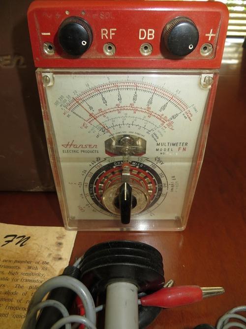
Old analog meters were feared for destroying semiconductors while testing, an exaggeration but with *some* basis: old semiconductors were very weak and meters usually had 1 or 2 1.5V batteries for ohms reading, some also hade a 9V one for "high ohms" (thing megohms) testing and my trusty old Hansen FN
had a (germanium) transistor and diode killing 22.5V battery , with not much current limiting if at all.
FWIW the long finned probe is to measure up to 25000 Volts DC, it could also read RF and Decibels , how's that?
 Tweet
Tweet


Comment