Announcement

Collapse
No announcement yet.

Adding a tone control to Red Llama clone

Collapse
X
 
  • Filter
  • Time
  • Show
Clear All
new posts

  • Adding a tone control to Red Llama clone

    I was the proud owner of a Way Huge Red Llama pedal for 30 days last summer courtesy of GC but ended up returning it. I just bought a WHRL clone and found the tone to be noticeably brighter and would like to add a tone trim pot to it (which might eventually end up as a side panel control.) BTW the Red Llama is Jeorge Tripps' version of the Craig Anderton Tube Sound Fuzz.

    Here is a schematic of a presumably different clone which I imagine would be similar in architecture. It would be easiest to add a simple variable resistor treble-cut tone control right on the output jack but probably better to insert it in-line to the input of the volume control (as I've seen on many pedal schematics.)

    My question is this: what values for the pot and capacitor would be a good starting point? While trimpots are usually linear what taper would be optimum for a panel pot?


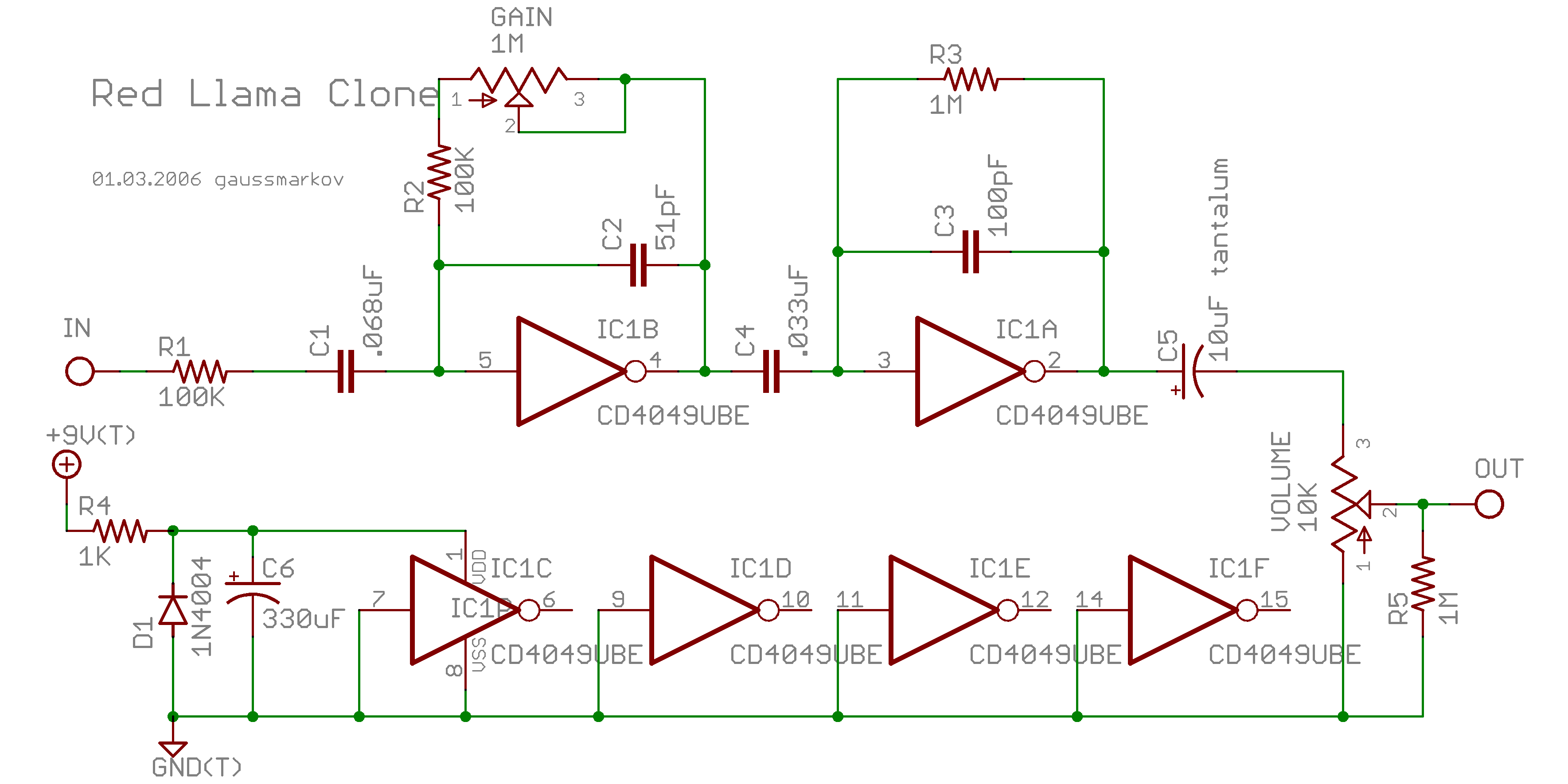
    http://gaussmarkov.net/layouts/redll...lama-schem.png

    Click image for larger version

Name:	redllama-schem.png
Views:	1
Size:	64.7 KB
ID:	870988

    %=%=%=%=%=%=%

    Here is one drawing of the Tube Sound Fuzz:


    Click image for larger version

Name:	tube sound fuzz.png
Views:	1
Size:	30.7 KB
ID:	870754


    Thanks!

    Steve Ahola

    P.S. So far for ss amps and pedals I've just been cutting and pasting ideas from one circuit to another (not to mention all of the great help I've been getting here at MEF!) but I have a fresh copy of my old culprit in crime coming in: The Op-Amp Cookbook! So I'll be able to better understand the ss circuits I'm looking at.

    P.P.S. In comparing the two drawings I guess that I should check the value of the two caps labelled C2 & C3 in the first drawing to see if they have the TSF values of 10pf or the WHRF values of 51pf and 100pf, respectively. That could explain why the clone pedal is much brighter and might make the added tone control unnecessary (I did not miss it with the real Red Llama.) BTW what is the big difference between the CD4049 or CD4069 and the more common op-amps used in FX pedals?

    EDIT 4:42PM PDT: I just checked the small pcb with 13 parts (add 2 pots, 2 jacks, a 3PDT footswitch, a battery clip and a DC jack and that is it!) and the ceramic cap nearest the index mark on the CD4049 going CCW is labelled 683 and the one further down is labelled 333. Quick reality check: a larger value cap in the NFB loop of an op-amp should cut more highs- right?

    The 3 tantalum(?)caps going CCW from index mark are labelled 16, 101 and 610, with only the first one having a plus mark to indicate polarity.

    So I guess that inserting a trimpot and capacitor at the output jack would be the easiest way to go, and once I determine the optimum values I could insert the treble-cut tone control ahead of the volume pot.
    Last edited by Steve A.; 10-03-2016, 07:56 AM. Reason: Re-uploaded Red Llama schematic 10/03/2016
    The Blue Guitar
    www.blueguitar.org
    Some recordings:
    https://soundcloud.com/sssteeve/sets...e-blue-guitar/
    .

  • #2
    A problem with capacitive loads on op amps is that they can sometimes result in instability; hence low value series resistors are often used between output stages and the, er, output. I learnt that the hard way, when the capacitance of a long instrument cable sent some in-guitar pre-amps I built into ultrasonic oscillation
    I guess the CMOS chips would probably be fine, as their open loop bandwidth is likely very low, but I'd be wary of that approach all the same.

    I suggest to replace the 1M feedback resistor of the 2nd stage with a 1M pot, with a cap between the wiper and 'output' terminals.
    Experiment with the cap value to achieve a nice range of control, suggest 220pF as a starting point.
    If there's a 10pF cap already across the 1M (maybe not as one doesn't seem to be included in your cap inventory of the board), leave it in circuit as it may be required to maintain stability; perhaps experiment with reducing its value, to give a bit more range to the new tone control.
    My band:- http://www.youtube.com/user/RedwingBand

    Comment


    • #3
      Okay, I guessed wrong about the caps. The ceramic caps labelled 683 and 333 are coupling caps, .068uF and .033uF. There is one 16uF tantalum cap going to the volume control. The "blob" caps 101 and 610 would be 100pF and 61pF, much closer to the Red Llama schematic.

      I did not check the values of the resistors or pots but everything else looks very close to the Red Llama except for a 61pF cap instead of a 51pf cap in the NFB loop of the 1st stage and a 16uF tantalum cap instead of a 10uF one between the 2nd stage and the output jack. Those changes shouldn't make much of a difference... perhaps the CD4049 used in the clone is brighter that the one in the WHRL pedal?

      The pedal sounds okay when plugged into another pedal with a tone control which can be turned down so I'm probably going to leave the PCB alone and add a treble-cut tone control to the output jack or ahead of the volume control. Any suggestions on what values I should try first?

      BTW the PCB appears to be glued to the back of one or both pots hence my reluctance to modify it.

      Steve Ahola

      EDIT: After reading the following TDPRI thread on Red Llama mods I guess I need to rethink my plan. Replacing the 61pf C2 cap with 120-150pf should cut down the brightness and replacing the 1M resistor in the loop of the 2nd stage with a 1M trim pot would allow me to dial down that stage. One other idea was to add a cap across the outside terminals of the level pot, but only if the PCB mods don't do the trick... any ideas what values to try first?

      http://www.tdpri.com/threads/red-lla...d-mods.189563/
      Last edited by Steve A.; 07-04-2016, 10:37 AM.
      The Blue Guitar
      www.blueguitar.org
      Some recordings:
      https://soundcloud.com/sssteeve/sets...e-blue-guitar/
      .

      Comment


      • #4
        We've worked this all out on the diystompbox forum. Just stick a SWTC tone control between the 10uf cap and the volume pot. There is more than enough output level from the unit that you can afford to sacrifice a bit of level to a passive control.

        AMZ Stupidly Wonderful Tone Control 2

        Comment


        • #5
          Originally posted by Mark Hammer View Post
          We've worked this all out on the diystompbox forum. Just stick a SWTC tone control between the 10uf cap and the volume pot. There is more than enough output level from the unit that you can afford to sacrifice a bit of level to a passive control.

          AMZ Stupidly Wonderful Tone Control 2
          Mark to the rescue! Since there is already too much brightness to my ears I looked up the earlier SWTC(1) treble-cut thread at DIYSB:

          Stupidly Wonderful Tone Control: cap value?


          With a 10k level pot it looks like I should use a 2.5k trim pot with a series resistor R1 between 120R and 270R.

          Looking at your example in the thread I would use a 0.039uF cap for "upper and lower points of 8.7khz and 390hz." Should I adjust the value of R1 to get the same frequency response with a more common 0.033uF or 0.047uF cap? At this point doing the math in my head is straining my brain. Or would it be better to just replace the 10k level control with something bigger to better fit the examples in your post?

          %=%=%=%=%=%

          Looks like I get to use my new $20 Joe Knows capacitor assortment that I picked up especially for stomp boxes! No sense using my 630vdc capacitor assortment for tube amps...


          https://www.amazon.com/gp/product/B0...?ie=UTF8&psc=1

          Along with my $18 kit of 1/4W metal film resistors from Joe Knows. Ditto for the collection of 1/2W MF resistors I put together at great expense for tube amps @ ~25 cents each in the skinny cardboard packaging. Ouch! Where was Joe with his 3 cent resistors when I needed him???

          https://www.amazon.com/Joe-Knows-Ele...f=pd_sim_328_2

          Here is a link to the 1/2W assortment for $25...

          https://www.amazon.com/gp/product/B006XGK05A

          BTW you can also buy these kits from the Joe Knows website:

          https://www.amazon.com/gp/product/B006XGK05A

          I wasted my money on the stupid Velleman resistor assortments of 10% carbon film resistors which didn't come in a handy cardboard box like this. (I don't think I ever found a resistor closer than 5% to the marked value so I think that Velleman was buying up lots rejected by QC.)


          Steve Ahola

          P.S. The first post in this thread makes it very clear that when comparing two schematics it works a lot better if the images are displayed within the post rather than as attachments that you must click on to view one at a time.

          I have instructions on how to do that in a sticky in the Lobby forum... or just send me a PM with a link to your post and I can edit your post for an in-line display.

          Also with all of the attachments lost here a few years ago if there is an image you want to attach and display in an old post send me a PM with a link to your post and to the image to be displayed. I've already done that for a few members here so I might as well offer to do that for anyone here (especially here in the Guitar FX forum where the drawings are usually pretty small.)

          As super moderator (not my choice!) I can edit any post but I have no idea as to the editing capabilities of regular members. It looks like you can edit your posts at least when they are still fairly new but I have no idea if and when your editing powers expires.

          P.P.S. Are SWTC 1, 2 & 3 your creation, Mark? I was thinking of adding a closed sticky in this forum with the drawings and some examples. If you want to write up the post I can insert the attached images in-line wherever you want them.

          (I have a keyboard macro that automatically inserts the 6 character string [/IMG] with a single click of my Android tablet which incidentally adds spaces before and after pasted text so I need to do a little editing anyway. AFAIK that is a characteristic of the Android OS which makes a lot of extra work for me. Boo!)
          The Blue Guitar
          www.blueguitar.org
          Some recordings:
          https://soundcloud.com/sssteeve/sets...e-blue-guitar/
          .

          Comment


          • #6
            1) Not my invention at all. I just popularized it with a catchy name. Sometimes, plain and simple things have more cachet with a snazzy name. The 2 and 3 configurations are Jack Orman's very clever ideas.

            2) The cap and R1 values will depend on what sort of control range you want/need. The F = 1 /[2 * pi * R * C] formula can be applied to identify the highest rolloff point (where the wiper is closest to R1) and lowest rolloff point (wiper closest to R3).

            3) The tone pot value will depend on the value of the volume pot following it, and how much passive signal loss you think you can afford. The addition of R1 and R2 chops the max output level, when combined with R3. The Red Llama normally has a fairly substantial output, so dropping the max output by a little over half, via a 10k pot as R2 and 1k fixed resistor as R1, is an acceptable loss. If it was something like a Distortion+, where the germanium clipping diodes severely limit max output, I would aim for a tone pot much lower in value than the volume pot.

            Comment


            • #7
              Originally posted by Mark Hammer View Post
              1) Not my invention at all. I just popularized it with a catchy name. Sometimes, plain and simple things have more cachet with a snazzy name. The 2 and 3 configurations are Jack Orman's very clever ideas.
              Let me rephrase that. Was it you who introduced the circuit to the DIY community suggesting that it be inserted into a stompbox design between the coupling cap and level control? I'm sure that the circuit had been in commercial pedals but did you popularize it with the snazzy name?

              Just wondering...

              Steve Ahola

              P.S. When I first looked at the SWTC diagram I wondered how the hell is THAT going to work... I could see how the cap to ground would bleed off high frequencies but how is it going to be adjustable?

              Yes, I don't understand SS electronics very well and have a shaky grip on the whole RC thing.
              But fear not... my replacement copy of The Op-Amp Cookbook should be delivered by the postman today so I won't have to keep bugging you guys so much.

              Steve A.
              The Blue Guitar
              www.blueguitar.org
              Some recordings:
              https://soundcloud.com/sssteeve/sets...e-blue-guitar/
              .

              Comment


              • #8
                Originally posted by Steve A. View Post
                Let me rephrase that. Was it you who introduced the circuit to the DIY community suggesting that it be inserted into a stompbox design between the coupling cap and level control? I'm sure that the circuit had been in commercial pedals but did you popularize it with the snazzy name?

                Just wondering...
                I won't say "yes, absolutely", but "probably" is a more accurate and tentative answer. Certainly, I christened it as the SWTC and the name gained traction. I've since seen that configuration in many schematics that long predate my little blip. The key thing is that unbuffered variable lowpass filters tend to lose signal amplitude when you raise the series resistance leading up to the bleedoff cap. The Proco Rat uses that sort of configuration, but inserts a FET buffer stage so there is no level-drop. I was looking for something that could be added pretty much anywhere that a person wanted to supplement a simple Volume control with a not-originally-included Tone control, but in a way that wouldn't require adding a buffer or involve sacrificing too much level. This ended up being a simple solution to that problem.

                Comment


                • #9
                  Originally posted by Mark Hammer View Post
                  I won't say "yes, absolutely", but "probably" is a more accurate and tentative answer. Certainly, I christened it as the SWTC and the name gained traction. I've since seen that configuration in many schematics that long predate my little blip. The key thing is that unbuffered variable lowpass filters tend to lose signal amplitude when you raise the series resistance leading up to the bleedoff cap. The Proco Rat uses that sort of configuration, but inserts a FET buffer stage so there is no level-drop. I was looking for something that could be added pretty much anywhere that a person wanted to supplement a simple Volume control with a not-originally-included Tone control, but in a way that wouldn't require adding a buffer or involve sacrificing too much level. This ended up being a simple solution to that problem.
                  It is ideal for a DIY or commercial clone pedal since they don't usually have board mounted pots so there would normally be no need to modify the circuit board. With the values as quoted below from an earlier post of mine is there a fairly neutral position for the 2.5k tone pot? Not that it matters in this case because the pedal is too bright. Period. I think I will stick to the value of 0.039uF by adding capacitors together unless you have a better suggestion. BTW I was reading how some NOS CDA4049s can sound better than some of the new ones. That could account for the differences from the clone pedal and my memory of the real McCoy from last summer. (My memory is that I didn't have to adjust downstream tone controls to get the sound I wanted.)

                  Looking at your example in the thread I would use a 0.039uF cap for "upper and lower points of 8.7khz and 390hz." Should I adjust the value of R1 to get the same frequency response with a more common 0.033uF or 0.047uF cap? At this point doing the math in my head is straining my brain. Or would it be better to just replace the 10k level control with something bigger to better fit the examples in your post?
                  Thanks again!

                  Steve Ahola
                  Last edited by Steve A.; 07-05-2016, 08:56 PM.
                  The Blue Guitar
                  www.blueguitar.org
                  Some recordings:
                  https://soundcloud.com/sssteeve/sets...e-blue-guitar/
                  .

                  Comment


                  • #10
                    Originally posted by Mark Hammer View Post
                    The tone pot value will depend on the value of the volume pot following it, and how much passive signal loss you think you can afford. The addition of R1 and R2 chops the max output level, when combined with R3. The Red Llama normally has a fairly substantial output, so dropping the max output by a little over half, via a 10k pot as R2 and 1k fixed resistor as R1, is an acceptable loss.
                    On second thought I think I will go with your suggestion of 10k for R2 and 1k for R1. To get something like your recommended "upper and lower points of 8.7khz and 390hz" if I'm doing the math right in my head I'd use a 0.01uF cap?

                    To make sure I have this correct with R1 set to 0 ohms we get the upper frequency point (cut-off frequency?) and with R1 set to 10k we get the lower frequency point.

                    As for the formula F = 1 /[2 * pi * R * C] with frequency in Hz what notation format would I use for R and C (like ohms or kilo-ohms, or farads or microfarads)?

                    Oops! I just found an on-line RC calculator but am a bit confused by the 1e-6 terminology in the box. Would 0.01uF be 1e-8?

                    RC Filter Calculator

                    Steve Ahola
                    The Blue Guitar
                    www.blueguitar.org
                    Some recordings:
                    https://soundcloud.com/sssteeve/sets...e-blue-guitar/
                    .

                    Comment


                    • #11
                      Originally posted by Steve A. View Post
                      On second thought I think I will go with your suggestion of 10k for R2 and 1k for R1. To get something like your recommended "upper and lower points of 8.7khz and 390hz" if I'm doing the math right in my head I'd use a 0.01uF cap?

                      To make sure I have this correct with R1 set to 0 ohms we get the upper frequency point (cut-off frequency?) and with R1 set to 10k we get the lower frequency point.
                      Check.

                      As for the formula F = 1 /[2 * pi * R * C] with frequency in Hz what notation format would I use for R and C (like ohms or kilo-ohms, or farads or microfarads)?

                      Oops! I just found an on-line RC calculator but am a bit confused by the 1e-6 terminology in the box. Would 0.01uF be 1e-8?

                      RC Filter Calculator

                      Steve Ahola
                      I just use megohms and microfarads. So a 10k tone pot value with a 39nf cap from the wiper to ground yields a rolloff beginning at 1 / (2 * pi * .01 * .039) = 408hz. If we tack on a 1k fixed resistor in series with the "input" lug of the tone pot, that switches to 1 / (2 * pi * .011 * .039) = 371hz. With the wiper moved over the other way so that there is only the 1k fixed resistor leading up to the wiper, the rolloff commences at 4,080hz. Depending on how you want to wire it up (clockwise = more cut, or clockwise = more treble) one might find that a log or antilog pot yields optimal dialability. It will still work with a linear pot, but preferred settings might be confined to a small arc of rotation.

                      Comment


                      • #12
                        Originally posted by Mark Hammer View Post
                        I just use megohms and microfarads. So a 10k tone pot value with a 39nf cap from the wiper to ground yields a rolloff beginning at 1 / (2 * pi * .01 * .039) = 408hz. If we tack on a 1k fixed resistor in series with the "input" lug of the tone pot, that switches to 1 / (2 * pi * .011 * .039) = 371hz. With the wiper moved over the other way so that there is only the 1k fixed resistor leading up to the wiper, the rolloff commences at 4,080hz. Depending on how you want to wire it up (clockwise = more cut, or clockwise = more treble) one might find that a log or antilog pot yields optimal dialability. It will still work with a linear pot, but preferred settings might be confined to a small arc of rotation.
                        I was going to use a trim pot, at least for now, so I better get a 28-turn one. So for audio/reverse audio taper which end of R2/P1 in the drawings gets bunched up?
                        While the ~8khz upper limit is more neutral ~4khz would be more appropriate here since I really don't need the stock sound of the RL clone.

                        Thanks!

                        Steve A.

                        EDIT Looking at the guts of the pedal again I think I'm going to build one with a SWTC tone control. I just ordered some NOS RCA CD4049UBF's from 1984 thinking that they might sound better. I guess I *could* replace the existing IC in the clone with a socket...
                        Last edited by Steve A.; 07-08-2016, 03:33 PM.
                        The Blue Guitar
                        www.blueguitar.org
                        Some recordings:
                        https://soundcloud.com/sssteeve/sets...e-blue-guitar/
                        .

                        Comment


                        • #13
                          Way Huge's latest pedal is the Camel Toe which stacks a Red Llama into their Green Rhino... and the Red Llama half has a tone control! Can't wait to see a schematic on how they are doing that...

                          Steve Ahola
                          The Blue Guitar
                          www.blueguitar.org
                          Some recordings:
                          https://soundcloud.com/sssteeve/sets...e-blue-guitar/
                          .

                          Comment


                          • #14
                            Myself, I like control, but I also like simplicity and repeatability. Sometimes it's simpler and easier just to use a 3-position toggle to select 3 different rolloffs; a "default" and two additional rolloffs via different treble-bleed caps.

                            In that circumstance, leaving a cap "floating" will result in audible popping when that cap is selected. The solution is actually pretty simple. Have each cap tied to ground via a 470k resistor, to bleed off any stored charge, and use the toggle to select which resistor to bridge/shunt.

                            You can do that with a SPDT on-off-on. If you want three more differentiated voices, use a DPDT on-off-on to select both a different treble cut on the output, AND a different treble rolloff in the second invertor stage.

                            Comment


                            • #15
                              Originally posted by Mark Hammer View Post
                              Myself, I like control, but I also like simplicity and repeatability. Sometimes it's simpler and easier just to use a 3-position toggle to select 3 different rolloffs; a "default" and two additional rolloffs via different treble-bleed caps.
                              True enough but it works better if you have actually auditioned the cap values rather than just guessing.

                              I like being able to dial in values with a tone pot as long as it doesn't load down the signal, even better if you can switch between different treble-bleed caps...

                              Thanks!

                              Steve A.
                              The Blue Guitar
                              www.blueguitar.org
                              Some recordings:
                              https://soundcloud.com/sssteeve/sets...e-blue-guitar/
                              .

                              Comment

                              Working...
                              X