Announcement

Collapse
No announcement yet.

Trace Elliot Brat Problem - OP Amp Question

Collapse
X
 
  • Filter
  • Time
  • Show
Clear All
new posts

  • Trace Elliot Brat Problem - OP Amp Question

    Hello,

    I have a repair job I'm doing on a Trace Elliot Brat combo amp at the moment. First the problem is that the signal is being lost. The gain has to be turned up really high to hear it at all and then the noise floor is very high. If the gain is turned up even higher a constant farting noise also appears.

    I traced the problem all the way back to the first amplification stage in the pre-amp with my oscilloscope. I've attached the schematic for reference. There is no signal output from IC2-A that will trigger the scope. With the scope probe on the + input (leg 3 of the IC) I see the input signal from the signal generator clearly while the amp is powered OFF. When I turn the amp ON the signal disappears from the screen completely. When I turn the amp OFF again the signal re-appears floating back down from the top of the screen to where it originally was.

    With my multimeter I see DC voltage of about -10V on both inputs. From researching OP amps I understand they amplify the difference between the inputs so having a significant DC voltage isn't a problem if it's roughly the same on both inputs? There is no significant DC voltage on either of the inputs of the next stage IC2-B. I'm also not sure why the input signal disappears from my scope when the amp is turned on and the DC voltage appears because the scope is on AC setting so it should be blocking the DC component anyway?

    Logically it seems obvious to me that the IC is bad and needs to be replaced as I cannot see what else it could possibly be. However, in case there's something I'm missing or not understanding here some input would be much appreciated as I don't want to go to trouble of replacing that part if it turns out not to be the problem.

    Thanks,
    Greg
    Attached Files

  • #2
    Can you post the DC voltages on all pins of the op amp?
    "I took a photo of my ohm meter... It didn't help." Enzo 8/20/22

    Comment


    • #3
      Leg 1 (out A): -10V
      Leg 2 (- in A): -9.9V
      Leg 3 (+ in A): -10V
      Leg 4 (Vee): -18.3V
      Leg 5 (+ in B): +18mV
      Leg 6 (- in B): +16.7mV
      Leg 7 (out B): -130mV
      Leg 8 (Vcc): +18.8V

      Comment


      • #4
        It sure looks to me like the op amp is shorted. I don't see a reason there would be DC on pins 1&2.
        "I took a photo of my ohm meter... It didn't help." Enzo 8/20/22

        Comment


        • #5
          Originally posted by GregS View Post
          With my multimeter I see DC voltage of about -10V on both inputs.
          That's not right. If it's IC2A then pins 1,2 and 3 should be at 0V DC not -10V. I'd change the opamp.

          Edit: I see The Dude beat me to it

          Comment


          • #6
            I'd pull that op amp then power up, and see if any odd voltage is sitting on those three pins where the IC used to be. Just to make sure the IC wasn't being driven to 10v.
            Education is what you're left with after you have forgotten what you have learned.

            Comment


            • #7
              Agree.
              That Op Amp is fed +/-18V rails so inputs and outputs should sit a few mV from Ground.
              Op Amp looks dead and I can see a reason why: + IN, pin 3 which is high impedance (so far so goos) is connected *straight* to input jack trough C20, with no series resistor which might somewhat limit possible current/voltage spikes.

              Owner may have connected some other ampspeaker out to Brat input ,obviously by mistake, or simply there was some static or power supply leak into a pedalboard or something and when plugging the spark killed the Op Amp.

              Or even something so common as plugging guitar cable into a pedal or active guitar, while plugging you have straight raw 9V DC at the plug tip for a fraction of a second.

              harmless to tube amps and most SS ones (which take some precautions against that) but here it´s somewhat unsafe, will work very well until killed

              As suggested above, replace that Op Amp, it may be the original RC4558 or a current standard TL072, both will work very well, but at least add a 22k to 68k resistor in series with C20.
              Just lift one leg out of the hole, insert 1 leg of the resistor there, then solder the free one to C20 free one.

              Jack>resistor>C20>pin 3

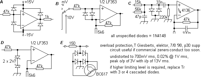
              IF you want to improve safety even more , use options A or D:


              Jack>22k>either diodes to +/-18V or back to back 2.7V Zeners to ground>C20>Pin 3

              Crate and Peavey always protect all inputs and even signal outputs this way, check some of their products, others rely on their rabbit´s legs for luck
              Juan Manuel Fahey

              Comment


              • #8
                For the pennies they cost, I always install an IC socket when I pull a chip out. Then check the empty socket under power just to be sure the voltages are correct, as per Enzo's suggestion.

                Comment


                • #9
                  Thanks for the input everyone. Whether I fix it or not depends on what the owner wants.

                  For the pennies they cost, I always install an IC socket when I pull a chip out. Then check the empty socket under power just to be sure the voltages are correct, as per Enzo's suggestion.
                  Actually, I plan to do that if I end up fixing the amp. The other two advantages are that there's no risk of damaging the part by overheating it when soldering and if the part were to fail again it's much easier to replace. It would be nice if manufacturers used sockets in the first place for these parts but I suppose in a mass produced product the extra step of inserting the IC's would add to the cost.

                  Thanks again everyone,
                  Greg

                  Comment


                  • #10
                    No, what it adds is a whole pile of potential poor connections. That is why they don't. Each IC pin is a connector, so if you have 10 ICs in an amp, you just added 80 connectors to it.
                    Education is what you're left with after you have forgotten what you have learned.

                    Comment


                    • #11
                      Some manufacturers did install sockets; Peavey with their mixer-amps and some power amps, Session and a few others I've seen. Plus, some studio gear is socketed throughout - such as the Arrakis X-mixer. I get the poor connection issue, but in practice I've not seen problems with socketed ICs in amps even after 30+ years of service. I see sockets as a convenience for the repairman, or where a chip would conceivably need to be swapped in the future or removed for reprogramming (such as PIC or EEPROM).

                      Comment


                      • #12
                        Yes, in the 1980s PV put then everywhere.

                        Certainly a programmed IC like a EPROM needs to be in socket. But much as I like convenience, the vast majority of ICs live their lives in the place they were first installed.

                        You are right, overall, those socketed amps didn;t seem more unreliable than soldered, but it only takes a small percentage of failures to increase your failure rate that small amount. As much as I saves me a few seconds to suck the old solder off an IC, when I repair things I also see the ICs pushed into sockets that caught a leg which folded under and never made teh connection. Then they bring it to me. "I changed the IC but it still doesn;t work."

                        Pick and place machines can install sockets as easily as ICs, before th board goes to wave solder. But then the board needs to go through pick and place again to have ICs stuffed in the sockets. Probably not a major expense.
                        Education is what you're left with after you have forgotten what you have learned.

                        Comment


                        • #13
                          Originally posted by GregS View Post
                          Thanks for the input everyone. Whether I fix it or not depends on what the owner wants.
                          Greg
                          Well, actually fixing it (not improving the design) takes all of 50 cents , whatever a TL072 costs.
                          Juan Manuel Fahey

                          Comment

                          Working...
                          X