I've been swapping tone stack values back and forth and they all sound good to me. Been trying 47K, 39K, 36K, and 33K slope. So I'm thinking about using a 50K pot instead. Been trying 470pF, 510pF, and 560pF treble caps. And same deal. They all sound good for various styles of music. I might just use the 510pF for a middle of the road value. Or I might throw some caps on a switch.
The thing is, I'm short for space on the chassis to mount the pot. I don't really use the Ceriatone "pussy trimmer". I always keep it maxed out. So I might hardwire a resistor in its place and use the mounting spot for the variable slope.
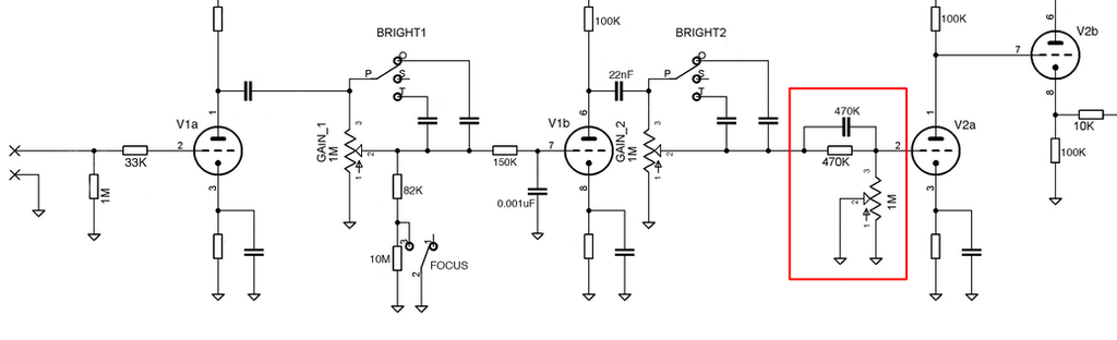
Just want to make sure all I need to do is measure the pot when it's on 100% and use a resistor that's close to that. Typically, 2204s have a 470K to ground as part of the treble peaking circuit. The pussy trimmer is a 1M pot that replaces that resistor. Just unsure what value resistor to use since the pot's value changes depending on where the gain control is set. But I'm guessing I should just use a 1M resistor since that's the pot's max value?
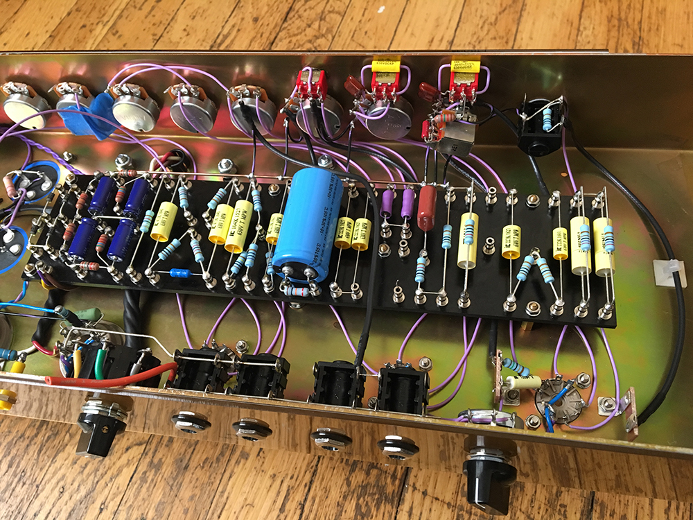
Hi FourT6and2, hope you're still checking in once in a while. Question for you if you have a minute. On your beautiful build, you use 3 chassis mounted jacks to park your bias check resistors. Can you tell me where to get those? Thanks! Mike
The only good solid state amp is a dead solid state amp. Unless it sounds really good, then its OK.
Hi FourT6and2, hope you're still checking in once in a while. Question for you if you have a minute. On your beautiful build, you use 3 chassis mounted jacks to park your bias check resistors. Can you tell me where to get those? Thanks! Mike
[ATTACH=CONFIG]47402[/ATTACH]
Both Mouser and Digi-Key will have them. Could also try Mojo, Antique Electronics Supply, and so on.
Those are probe tip sockets, sometimes called pin sockets, phone tip sockets, etc. Many years ago your headphones came with two wires with metal pins on the ends. Multimeters back in the day used these rather than today's banana jacks.
GO to Mouser and enter TIP JACKS in the search box. Then select test equipment accessories. Voila.
Education is what you're left with after you have forgotten what you have learned.
Hi Catalin, Thanks for the ground drawing. I can understand everything except where the wire is going that is labelled "use a thick wire as a bus line". This wire starts at the ground lug on one of the caps, then goes up to the right.
misread the drawing. I looked through the photos again, and I think it must go to the bus that rides along the side of the turret board where the cathode wiring gets grounded. Should the bus wire be in two pieces, one of the preamp tubes, and one part for the phase inverter ground that comes through the feedback resistor?
Feedback path is a signal path and have nothing common with the bus (except its safety function) but more with the stage it is related.It is usualy a loop including secondary OT coil nfb resistor and cathode resistor-or a tail like Fender PI- of the stage where is applied. You don.t need to include something else in those circuit. Turn the nfb return (meant common OT secondary) directly from isolated output jack to those local ground point. (eg: if you apply nfb to PI turn the nfb return wire to PI local grounding point). Think circles
Feedback path is a signal path and have nothing common with the bus (except its safety function) but more with the stage it is related. Turn the feedback wire directly at those stage local common signal point. (eg: if you apply nfb to PI turn the nfb wire to PI local signal grounding point)
OK thanks. I think I got it.
The only good solid state amp is a dead solid state amp. Unless it sounds really good, then its OK.
Relative to other question maybe you understand better from this pic why need to have care how to design the bus.
Those capacitors decoupling points should be tied to 0V potential relative to the ground. As time you bus present residual resistance (and it does) you wil get no 0V anymore due to the return currents over it. Noise will be occur rising directly onto control grids. From ground understand whatever you choose to be as reference, Any local decoupling points are related to those ground no matter how many stages or devices you run into the chain,
As you see second grid leak resistor belongs to both circuits: AC load for the first and DC grid reference for the second stage as well . From a noise pespective its position is better to be keeped close to second stage and tied to those local decoupling point. Large plains or big section conductor helps but is a must to keep order to try to isolate the return currents as much possible. Any basic principles to build a bus rail was well explained here on MEF and well knowed Merlin B article as well
Also be aware this local grounding spots are not equal in term of noise cause it run AC ripple. So have care what you extra tie to or from those points trying to use it like 0V reference. Is a matter of understanding then you can design any grounding scheme you want as it is a compromise in the end. So don.t copy the physical schemes, some works better in some cicumstances some in the other...but assume the basic principles to build your own
PS: in the past trying to optimise the physical grounding on my projects wiring in different ways I found there are not semnificative diferences in term of noise but more important different appetite for EMI couplings. This is another chapter need to be assumed
Edit: double post, please erase
"If it measures good and sounds bad, it is bad. If it measures bad and sounds good, you are measuring the wrong things."
 Tweet
Tweet
Comment