Announcement

Collapse
No announcement yet.

Valco speaker field coil windings

Collapse
X
 
  • Filter
  • Time
  • Show
Clear All
new posts

  • Valco speaker field coil windings

    I have a Valco 51 amplifier for repair. Thanks to the forum I've correctly identified the amp., but this is the first time I've come across this use of a field coil on the speaker.
    One of the issues is a dominant low level hum which remains present when the volume is turned right down.
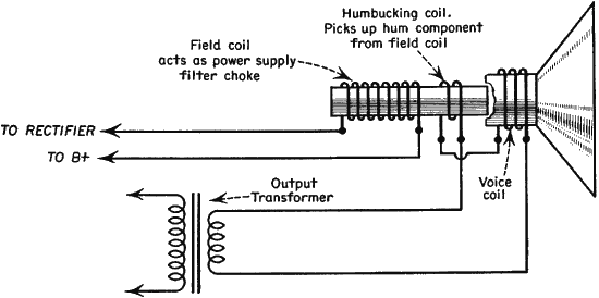
    I'm beginning to suspect the circuit involving the field coil.
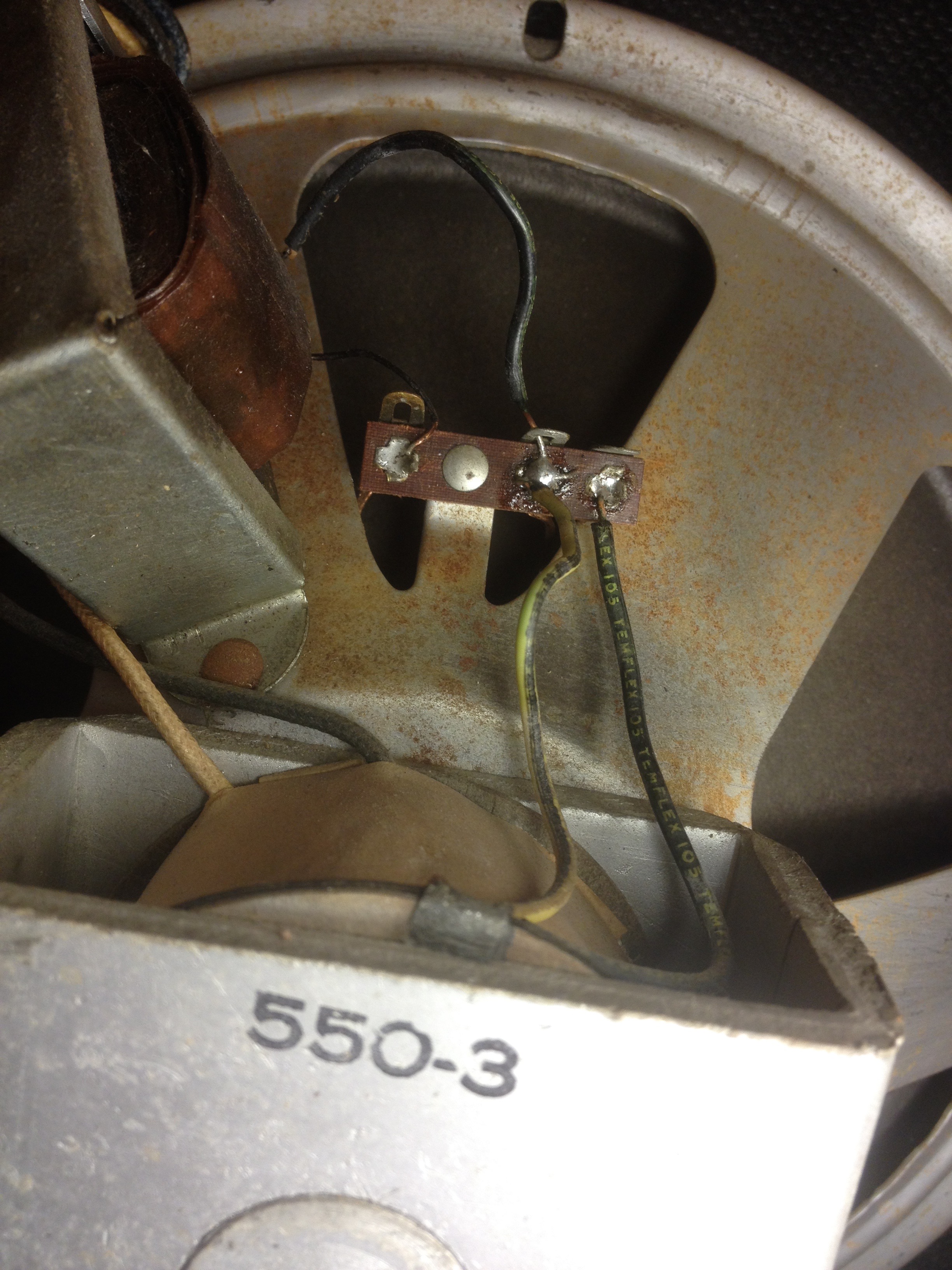
    One side of the voice coil is shown on the schematic to be connected to earth, but this is absent on the amp.
    The connections to the field coil are clear to understand but there is also a pair of wires (another winding?) coming from the top of the field coil and connected only on one side to the voice coil.
    There appears to have been work done replacing caps, on this amp, and some resoldering of the speaker and field coil connections at the amp, so I don't know if there is a mis-wire?
    Click image for larger version

Name:	Valco51.jpg
Views:	1
Size:	1.61 MB
ID:	873445Click image for larger version

Name:	Valco51.jpg
Views:	1
Size:	1.61 MB
ID:	873445
    Last edited by MzunguSteve; 03-21-2018, 05:58 PM.

  • #2
    Schematic?
    Education is what you're left with after you have forgotten what you have learned.

    Comment


    • #3
      A few schematics that may help.

      Click image for larger version

Name:	Supreme with tone control.jpg
Views:	2
Size:	462.8 KB
ID:	849059

      Click image for larger version

Name:	Valco510-1C.jpg
Views:	1
Size:	68.8 KB
ID:	849061

      Valco51.pdf

      Comment


      • #4
        Thanks. I have the schematic for the 510 with 6J7 input valve.
        Its the top winding on the speaker.
        I need to know how it should be connected.

        Comment


        • #5
          It's a sort of humbucking coil. I have a model 50 prewar (schematic doesn't quite match) here and have the same setup. I can see how this is wired, i may have redrawn the schematic.

          Comment


          • #6
            Can you post more pics of all the wires coming out of the speaker assembly and where they are going?
            And the little terminal board on the speaker with the three lugs, what connects to the back side of the far right lug where the temflex 105 wire is going?
            Originally posted by Enzo
            I have a sign in my shop that says, "Never think up reasons not to check something."


            Comment


            • #7
              Originally posted by g1 View Post
              Can you post more pics of all the wires coming out of the speaker assembly and where they are going?
              And the little terminal board on the speaker with the three lugs, what connects to the back side of the far right lug where the temflex 105 wire is going?
              The right hand black wire is not connected..
              This photo may help explain things. It’s from a Gretsch amp of the same period and pretty much the same circuit layout apart from the input valve.
              You’ll see the coil in question is in series with the voice coil in this case.
              Click image for larger version

Name:	F96D2F77-DF26-4630-B79E-67631878DEBE.jpeg
Views:	1
Size:	273.0 KB
ID:	849076

              Comment


              • #8
                Really all you need is 4 wires.
                Two for the voice coil & two for the field coil.

                If there are six wires then you have a 'humbucking' coil.
                This goes in series with the voice coil.
                The polarity of the hum bucking winding is important... in one direction it will reduce the hum... if reversed it will increase the hum. Make sure you have the voice coil and hum bucking coils in series, and wired for the least amount of hum! It is easy to check by ear.

                dynspkr.pdf

                Click image for larger version

Name:	Speaker_exploded_view_k.png
Views:	2
Size:	22.0 KB
ID:	849079

                Comment


                • #9
                  Originally posted by MzunguSteve View Post
                  The right hand black wire is not connected..
                  You mean that lug does not connect to anything on the back side? So where does that wire go at it's other end?
                  Originally posted by Enzo
                  I have a sign in my shop that says, "Never think up reasons not to check something."


                  Comment


                  • #10
                    Never mind, I think the black OT wire that connects to the second lug should be connected to the third lug like in the gretch amp pic you posted.
                    Originally posted by Enzo
                    I have a sign in my shop that says, "Never think up reasons not to check something."


                    Comment


                    • #11
                      Originally posted by Jazz P Bass View Post
                      Really all you need is 4 wires.
                      Two for the voice coil & two for the field coil.

                      If there are six wires then you have a 'humbucking' coil.
                      This goes in series with the voice coil.
                      The polarity of the hum bucking winding is important... in one direction it will reduce the hum... if reversed it will increase the hum. Make sure you have the voice coil and hum bucking coils in series, and wired for the least amount of hum! It is easy to check by ear.

                      [ATTACH]47747[/ATTACH]

                      [ATTACH=CONFIG]47748[/ATTACH]
                      Many thanks for the exploded diagram. I was wondering if humbucking was its purpose.
                      The Valco 51 has the upper, humbucking, coil.
                      From its appearance some resoldering has been done and the humbucker coil is not connected.
                      Will for continuity first.

                      Comment


                      • #12
                        Originally posted by g1 View Post
                        Never mind, I think the black OT wire that connects to the second lug should be connected to the third lug like in the gretch amp pic you posted.
                        Agreed, as Jazz P Bass suggests. Exploded diagram shows its purpose.
                        Many thanks.

                        Comment


                        • #13
                          Juan Manuel Fahey

                          Comment


                          • #14
                            Thanks for this helpful diagram.

                            Comment


                            • #15
                              We'll be interested to hear the results of connecting it, and if possible, connecting it both ways (phases). I'd expect one way will introduce even more hum than what is there when it is not connected, but I'm only speculating.
                              Originally posted by Enzo
                              I have a sign in my shop that says, "Never think up reasons not to check something."


                              Comment

                              Working...
                              X