 Tweet
Tweet
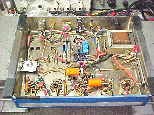
I�m now getting failures on the 5AR4 rectifier tube on the re-build/modified 20W E.H. Scott 510 Power Amp that my client is hoping to have increased power output from. The output stage is cathode biased, using 6L6GC�s, with a fixed 170 ohm 5W cathode resistor mounted to the floor, and the output of the 5AR4 rectifier tube feeds the first stage of a dual 50uF/500V F & T cap can thru a chassis-mounted 370 ohm 5W resistor.


510 SCHEMATIC-3.pdf
The existing current load is 159mA�145mA thru the power tubes (72.5mA/tube), and the rest thru the driver & preamp tube stages. At present, I don�t have a wide range of power resistors suitable to add in series to the cathode resistor of the power tubes, and my Clarostat Decade Power Resistor box is hidden in storage somewhere. Neither of my precision decade resistor boxes on hand have the current rating to lend a hand without being damaged. My thought yesterday was, after reading thru the Amperex 5AR4 data sheet, stating the need for a minimum of 125 ohm series resistor ahead of the first filter cap with 800VAC CT feeding the rectifier plates, that I�d decrease the 370 ohm R1 resistor with a pair of 470 ohm 5W resistors across it (net result 144 ohms), and take quick readings of the supply voltage at C1/R1 and the cathode resistor voltage @ R17, and shut it down.
5AR4-Amperex.pdf
Watching the supply voltage meter monitoring C1, the cathode voltage meter monitoring R17 and the AC Ammeter of the power analyzer while the 5AR4 begins waking up and starts ramping the supply voltage up, the rectifier tube flashed, fuse blew, before I even saw any significant readings. New rectifier tube.
Now, my gut feel is to first increase the value of R17 from 170 ohms to maybe 330 ohms, reducing the main current load on the power supply, since part of the exercise is to get the supply voltage up higher for greater output voltage swing. I�ve been somewhat bothered by the high plate current & power dissipation on these 6L6GC power tubes with the existing circuit values that I inherited in the unit. I�ve also wondered why E.H. Scott selected such a high plate voltage for the rectifier tube. The original rectifier tube used is a 5Y3GT, same 370 ohm series resistor to C1, which was a 20uF/450V cap, part of a 4-section cap can. The inductor wasn�t part of the power amp supply, but instead part of the preamp supply that was removed from this chassis. I thought I had measured the inductance value on my GR Digibridge, but found I had failed to record that detail.
I�ve attached the latest schematic of the amp, Amperex 5AR4 data sheet.
Comment