Announcement

Collapse
No announcement yet.

Phase inverter issue

Collapse
X
 
  • Filter
  • Time
  • Show
Clear All
new posts

  • Phase inverter issue

    I'm still having trouble with my bassman build (schematic). I've been poking at different spots with a scope looking for things that look odd. Below is a shot of the phase invert plates with the preamp signal grounded out.


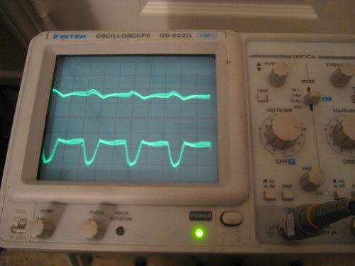
    The upper signal is V2b plate (the triode which inverts the output of the V2a triode) and it isn't what concerns me. The lower signal is what worries me. Its period is about 120 Hz and it looks kind of like a clipped sine.

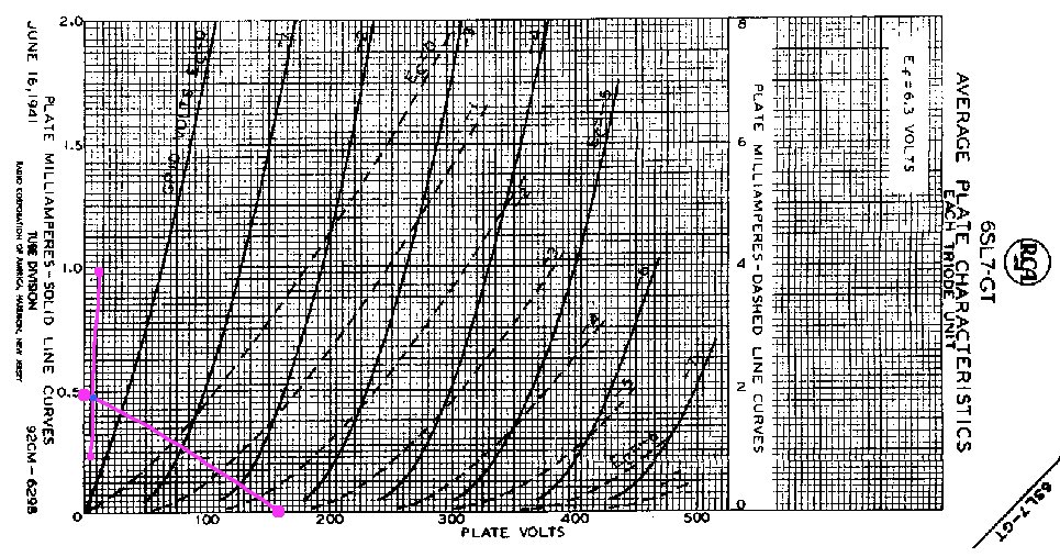
    I plotted the plate and cathode load lines crudely (below) and I think this triode is biased in cutoff. My plate and cathode voltages are 164 and 2.44 V, respectively. Did I plot this correctly?


    Thanks for the help.
    Check out my signal generator for your iPhone or iPod Touch.

  • #2
    For fun... drive the PI with a little signal so the output is say, around 30vac PP.
    Place your two two scope probes across the two PI plates (after the coupling caps) and mix the two channels together... the difference should distortion.
    As you crank the drive signal you'll see all kinds of odd stuff happening and sometimes that is a bit of the "magical guitar amp tone" many players are looking for.
    Bruce

    Mission Amps
    Denver, CO. 80022
    www.missionamps.com
    303-955-2412

    Comment


    • #3
      What is the amplitude of those traces?
      That link has too many http.
      Have you soldered the ground end of R13 25ohm global feedback return resistor to the grounded end of R6 5k V2B cathode resistor? If not try that, as any voltage between those 2 points will be seen as an input signal.
      That schematic has no grid stoppers - might your troubles be caused by oscillation? Peter.
      My band:- http://www.youtube.com/user/RedwingBand

      Comment


      • #4
        The clipped signal is about 20 mVpp. Well, peak-to-flat I guess you'd call that. By total chance R13 and R6 are grounded together. It gets dwarfed by preamp hum when the volume is non-zero so maybe it's not a big deal, but the shape bugged me.

        Bruce, that was fun actually. I took a couple videos, the first of just the two PI outputs and the 2nd of those two outputs summed.

        http://www.youtube.com/watch?v=ll679Ag_EPM
        http://www.youtube.com/watch?v=VqE_UMykTKI

        I can see that one side is a little larger than the other. My understanding is this can be tweaked by adjusting R14. I'm not sure how close is close enough, I don't have an issue with the general sound of the amp.

        Out of curiosity, can the PI stage be used to generate distortion on purpose? Does it sound good?
        Check out my signal generator for your iPhone or iPod Touch.

        Comment


        • #5
          The load line is not drawn correctly. It should go from (X,Y):

          B+ voltage of the tube, 0mA
          0V, B+/plate resistor
          WARNING! Musical Instrument amplifiers contain lethal voltages and can retain them even when unplugged. Refer service to qualified personnel.
          REMEMBER: Everybody knows that smokin' ain't allowed in school !

          Comment

          Working...
          X