Ad Widget

Collapse

Announcement

Collapse
No announcement yet.

Yup, Another One... Kraken 50 Build: Round II

Collapse
X
 
  • Filter
  • Time
  • Show
Clear All
new posts

  • #31
    Originally posted by mikepukmel View Post
    Somebody write a long post, I can't remember where. I don't know if they are a guru or not. They said, for the Fender style chassis anyway (and I know this is not that style), there were two main ground points. One near the power transformer, that had the HV stuff grounded directly to the chassis. Another on that brass plate that the pots and input jacks mount to, that the low signal wiring (input jacks, preamp tubes) get grounded to. They said that the eddy currents were separated enough, first since there are two different pieces of metal (the steel chassis, and the brass plate), and 2 they were grouped together in separate areas of the amp, that the amp would still be OK for hum and noise due to ground loops. Admittedly, I don't have the physics chops at hand to be able to understand this argument fully. Was it a baloney argument?
    No, more than one ground point can certainly work with careful testing and layout. I would speculate that Fender had the resources to get it done properly, with as low a parts count as possible.

    The reason for having more than one ground point could be due to wanting the input connectors grounded directly. In the fifties it was quite common in the US that small towns had their own AM radio station transmitting in the range of 500-1700 kHz, as FM stations were not nearly as widely used as they were in Europe at the time. If a strong, local AM radio station were present in the neighborhood, then it could easily be picked up by the external wiring to the guitar etc. Having the input connectors grounded directly to the chassis would be quite beneficial to help reduce interference problems, despite the potential for problems with ground loops. If the inputs were floating, you'd have to connect the cable shields to chassis ground at the input via a bunch of low-ish value capacitors. The caps should have a low impedance for RF yet a high impedance for audio and mains hum. This would be more expensive and less reliable due to the higher component count. So using the resources to get the grounding right would be beneficial with no downsides.

    I would further speculate that the potential for AM radio interference was also the reason why Fender et al. used those very high value grid stopper resistors, noisy as they are, though that is probably a subject for a different thread. (This has probably been discussed at length before here on M-E-F.)
    Comment


    • #32
      Originally posted by FourT6and2 View Post
      So which of these two is better?
      Top.

      Not-very-ninja-edit: Strictly speaking the answer would depend on how you connect the rest of the amp to the pair of filter caps.
      Last edited by Thoriated Tungsten; 08-05-2017, 04:23 PM.

      Comment


      • #33
        Originally posted by Thoriated Tungsten View Post
        Top.

        Not-very-ninja-edit: Strictly speaking the answer would depend on how you connect the rest of the amp to the pair of filter caps.
        I'm basically following the Ceriatone layout, which for the most part stays true to how Marshall did it in a 2204: http://www.ceriatone.com/ceriatone/w...-June-2015.jpg
        Last edited by FourT6and2; 08-05-2017, 04:45 PM.

        Comment


        • #34
          Attached Files
          "If it measures good and sounds bad, it is bad. If it measures bad and sounds good, you are measuring the wrong things."

          Comment


          • #35
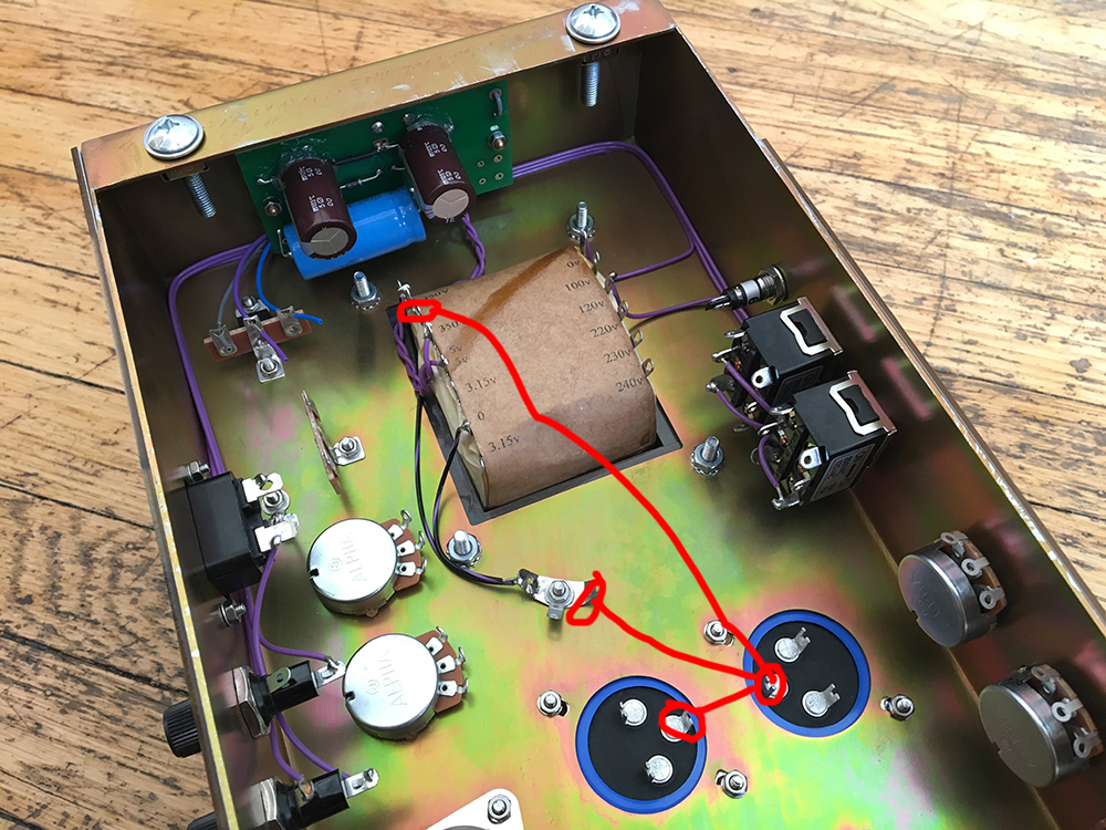
            I would definitely lift the grey '0' wire on the 2x 350V secondary from the star ground and have it follow A1 & A2 over to the bottom of the 220k bleeder resistor on the top filter cap. There is zero benefit to having the HT center tap going to the star ground. Right now the full ripple current from the transformer is flowing through a wire carrying signal current (the green wire from the bottom cap to the star ground).

            Note that the low voltage supply for the DC heaters does things correctly by isolating the ripple currents from the chassis ground.

            Comment


            • #36
              Originally posted by catalin gramada View Post
              [ATTACH=CONFIG]44366[/ATTACH]
              Interesting. So you're using the reservoir cap's negative terminal as a mini star node. Then sending that to ground instead of the screen cap's neg. Like this:

              Comment


              • #37
                Originally posted by Thoriated Tungsten View Post
                I would definitely lift the grey '0' wire on the 2x 350V secondary from the star ground and have it follow A1 & A2 over to the bottom of the 220k bleeder resistor on the top filter cap. There is zero benefit to having the HT center tap going to the star ground. Right now the full ripple current from the transformer is flowing through a wire carrying signal current (the green wire from the bottom cap to the star ground).

                Note that the low voltage supply for the DC heaters does things correctly by isolating the ripple currents from the chassis ground.
                Great, thanks for the help!

                Comment


                • #38
                  Yes. Tie power cathodes at the wire between those two caps, You can use a thick solid wire between caps (or better one piece from first cap-second cap- third cap minus pole) and regular wires from power cathodes

                  Click image for larger version

Name:	ground scheme.jpg
Views:	1
Size:	34.9 KB
ID:	846087
                  "If it measures good and sounds bad, it is bad. If it measures bad and sounds good, you are measuring the wrong things."

                  Comment


                  • #39
                    Originally posted by catalin gramada View Post
                    Yes. Tie power cathodes at the wire between those two caps, You can use a thick solid wire between caps (or better one piece from first cap-second cap- third cap minus pole) and regular wires from power cathodes

                    [ATTACH=CONFIG]44369[/ATTACH]
                    Oh I see you're bringing the preamp ground from the bus bar to the screen filter cap negative as well, instead of directly to star ground?

                    Comment


                    • #40
                      that.s right. But there are also some wires you need to move to complete: inverter ground (green wire from presence cap) should be tied to minus pole of second cap and NFB return (the wire from output jack to chassis) lift from chassis and tie at the presence pot lug.
                      Last edited by catalin gramada; 08-05-2017, 06:14 PM.
                      "If it measures good and sounds bad, it is bad. If it measures bad and sounds good, you are measuring the wrong things."

                      Comment


                      • #41
                        Originally posted by catalin gramada View Post
                        that.s right. But there are also some wires you need to move to complete: inverter ground (green wire from presence cap) should be tied to minus pole of second cap and NFB return (the wire from output jack to chassis) lift from chassis and tie at the presence pot lug.
                        So, I get why—technically—these things are good to do. But there is no noise in this amp. The amp is pretty quiet already. So what exactly will these things improve?

                        Comment


                        • #42
                          This is a very good question. The designers spend a lot of effort to simplify the building choosing the best compromise to do a proper grounding (and you circuit have a lot)Someone clever find a way to broke the rule and made a functional circuit despite the wiring bugs. The wiring plan I presented to you guarantee the minimal noise in you circuit from a grounding point. There is no reason to change anything in you amp if you amp works without grounding issues...I don.t remember how this discusion started on...
                          Last edited by catalin gramada; 08-05-2017, 06:43 PM.
                          "If it measures good and sounds bad, it is bad. If it measures bad and sounds good, you are measuring the wrong things."

                          Comment


                          • #43
                            Originally posted by catalin gramada View Post
                            This is a very good question. The designers spend a lot of effort to simplify the building choosing the best compromise to do a proper grounding (and you circuit have a lot)Someone clever find a way to broke the rule and made a functional circuit despite the wiring bugs. The wiring plan I presented to you guarantee the minimal noise in you circuit from a grounding point. There is no reason to change anything in you amp if you amp works without grounding issues...I don.t remember how this discusion started on...
                            hahaha understood

                            There are a few things I can rewire, like the PT center tap to the reservoir cap instead of chassis ground. But there are some other compromises I have to make just due to lead dress and whatnot. The entire preamp is isolated and grounded to a floating bus bar, with one connection to the star ground. But I have the output tubes grounded locally through external bias test points. That can't change.

                            Comment


                            • #44
                              I won't comment on either or,.. but would like to know if you hear any difference - since are building two!?

                              Comment


                              • #45
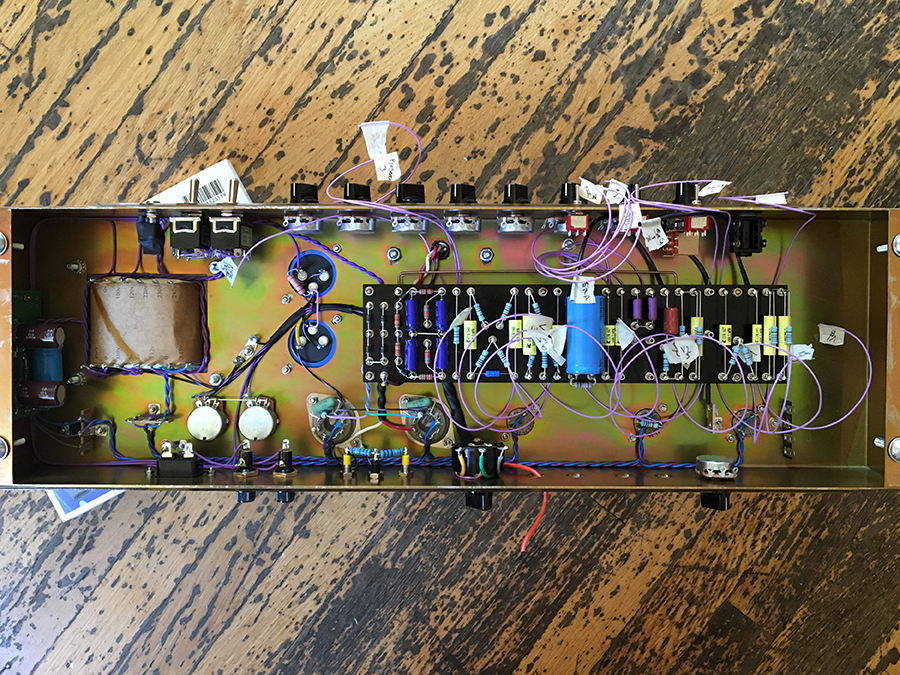
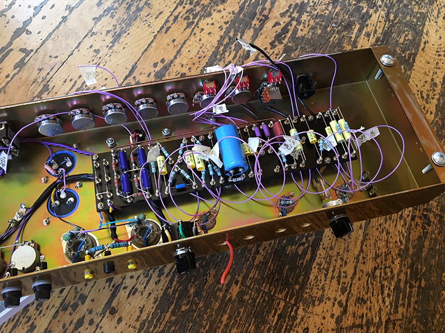
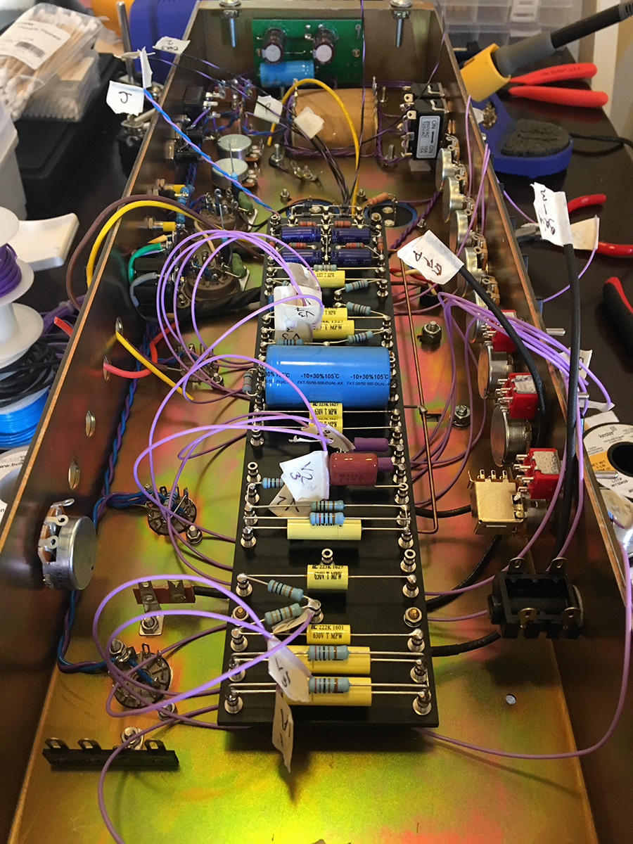
                                Some more progress today. This is the part where everything's a hot mess lol. Redid some of the grounding as discussed. Reservoir cap neg. lug now serves as a floating star ground. That point goes to chassis ground. So just one wire to chassis for the most part. There are still one or two local grounds, but that is unavoidable. Preamp ground bus goes to screen supply neg. lug. That goes to reservoir cap neg. lug. PT CT goes to reservoir cap neg. lug. Bias pots and filament CT go to chassis ground point. Didn't wire those to the floating star ground because it would have been a cluster fuck.


                                Comment

                                Working...
                                X