Ad Widget

Collapse

Announcement

Collapse
No announcement yet.

Layouts... how to... from schematic to layout to handwired amp.

Collapse
X
 
  • Filter
  • Time
  • Show
Clear All
new posts

  • Layouts... how to... from schematic to layout to handwired amp.

    damn silly question i'm sure but I have to ask....

    I'm planning on rebuilding a laney LC15. The amp I have eats power transformers without blowing fuses but I cant see any shorts or low resistance points with the dmm so.....

    rather than repair the pcb, I was going to build it as a point to point type layout with nos components.

    Before I crash into it though, i was wondering about those nice neat component layouts and how people go about making them up. is it just a case of starting from the input jack and working along, drawing as you go, or from the other end and working back or is there another method people use? is there a bit of software that can be used or is it some other magic?

    any pointers gratefully received.

    George
  • #2
    Usually a good part of the job is already done !!!
    Unwritten convention draws schematics left to right, from input to output, with signal level increasing along the way.
    Some schematics draw preamp on top and Power amp and supply on the bottom, but they are clearly recognizable as a "long" drawing which was split to fit a rectangular sheet of paper (or computer screen) in a more efficient way.

    So in a nutshell start "redrawing the schematic" left to tight but drawing actual part outlines somewhat real sized instead of the plain symbols, and soon youŽll have a very rough first layout distribution.
    Draw a long narrow rectangle on top end to end and a similar one along the bottom (these will be front and back panels) and place all pot/switch/fuse/IEC outlet/pilot light/jacks , etc. along them.
    Soon youŽll be "seeing" what the amp will look like, in real life.

    As mental practice, look at a couple classic Fender Schematics and Layouts and it will all "click" at once.

    Complex SS amps follow similar rules, look (again) at some Fender schematics and layouts.

    Start with relatively simple "starter" amps, those typical 15W ones.
    Juan Manuel Fahey

    Comment


    • #3
      Thanks for the reply.

      Its pretty much what I have started doing, working from the input. looking at the schematic, i was wondering about lifting the ac15 back end and the jcm front end layouts and joining them the way laney has but decided that a clean version from scratch would be better.

      is there a favoured computer package for layouts or is it just whatever drawing package you have? i wondered if there was something with component shapes already built in rather than draw each box by hand every time.
      At least amp schematics are logical left to right... most hf radio schematics are just all over the place!

      Thanks again for the reply.

      George

      Comment


      • #4
        I use MS Paint and have created a bunch of components myself. Why? I don't like the other programs and it's simple simple simple to use. As an example, the attached schematic is one I just did a few weeks ago. I've even done layouts with it and it works just as well for that.
        Attached Files
        --Jim


        He's like a new set of strings... he just needs to be stretched a bit.

        Comment


        • #5
          For schematics, I use PCB express (I think that's what it's called) because the price was right.

          For layouts, so far my work's been all freehand, and I'll actually 'lay out' some of the big components and trace around them to make sure the layout is true. As far as theory behind the layout goes, I'm just a beginner myself, and JM's comment about looking at existing layouts rings true. There are also plenty of threads here about layout with respect to grounding, de-coupling, and other stuff.
          If it still won't get loud enough, it's probably broken. - Steve Conner
          If the thing works, stop fixing it. - Enzo
          We need more chaos in music, in art... I'm here to make it. - Justin Thomas
          MANY things in human experience can be easily differentiated, yet *impossible* to express as a measurement. - Juan Fahey

          Comment


          • #6
            this is a pretty usefull program:
            https://code.google.com/p/diy-layout-creator/

            goes from schematic to layout

            I use Diptrace or Eagle for straight PCBs

            Comment


            • #7
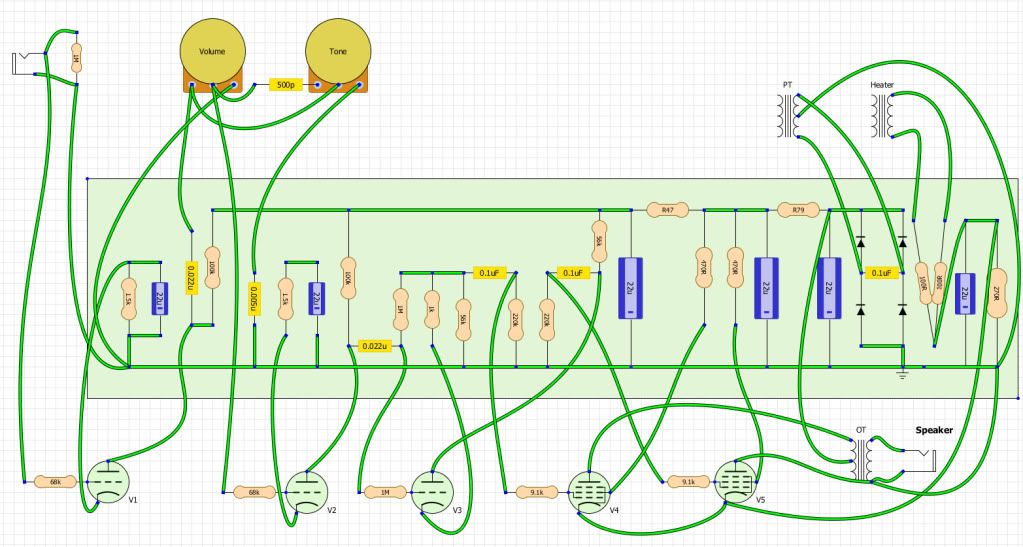
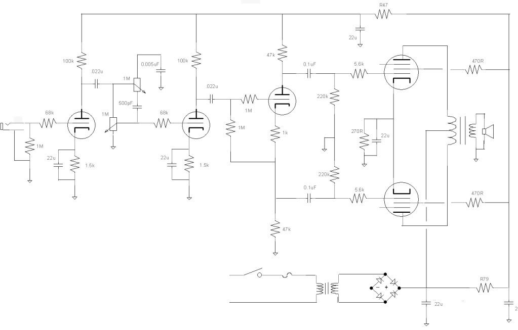
              Simple P-P amp, missing ground symbol on the bridge rectifier though.


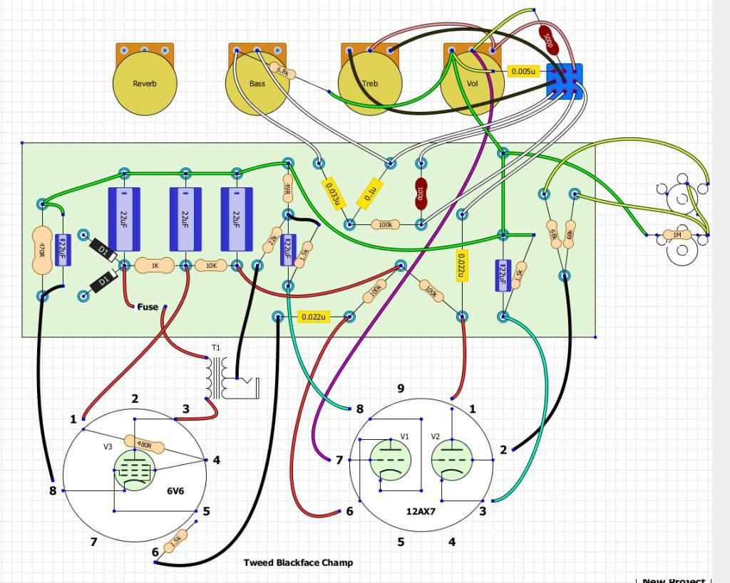
              Layout with diy layout creator


              Not a true layout in that the tubes are stile symbols rather than a circle with pins.

              Closer yet. Tweed and BF Champ.


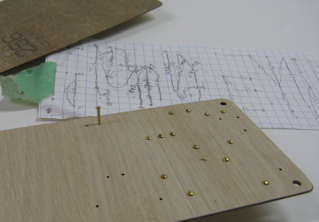
              Grid paper is one way to go also, good to have an eraser though.


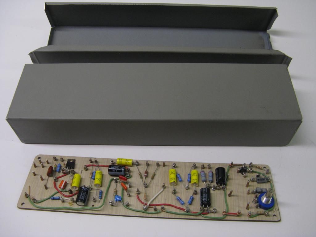
              Above work in process. Would rearrange things if I were to make a second.

              Comment


              • #8
                I do like pin idea! I have taken the 18w tmb schematic and copied it into diy layout creator. my problem is one of space, fitting the turret board between the two transformers. I will use some tag strip to move a few components around to make it all fit, and also mount some components straight on the pots/jacks.

                Thanks for the info!

                Comment


                • #9
                  Originally posted by gui_tarzan View Post
                  I use MS Paint and have created a bunch of components myself. Why? I don't like the other programs and it's simple simple simple to use. As an example, the attached schematic is one I just did a few weeks ago. I've even done layouts with it and it works just as well for that.
                  Man, I need to go to your "Paint" school. lol
                  That's nice work. Guess I should give that app a bit more credit than what I do, as I've always viewed it as a doodle-app since win95?-98? It's come a long ways.

                  Knowing you used Paint, and looking at my Jen wah pics recently...makes me feel like I'm still using the "crayons" version. Looks like this old dog needs to brush up a bit.
                  Start simple...then go deep!

                  "EL84's are the bitches of guitar amp design." Chuck H

                  "How could they know back in 1980-whatever that there'd come a time when it was easier to find the wreck of the Titanic than find another SAD1024?" -Mark Hammer

                  Comment


                  • #10
                    Originally posted by Slamdog View Post
                    Before I crash into it though, i was wondering about those nice neat component layouts and how people go about making them up. is it just a case of starting from the input jack and working along, drawing as you go, or from the other end and working back or is there another method people use? is there a bit of software that can be used or is it some other magic?
                    Any graphics program will do. Perhaps the most effective way to do it fast is to draw out some lifesized component bodies representing the parts you're going to use, then print some graph paper the size of your cabinet insides. Also on the graph paper, print the controls and jacks on the front panel and the switches and jacks on the back. OK, shoot, print the locations of the tube sockets too.

                    The controls, jacks, sockets, etc are mechanically fixed, and although you can change them, it'll be a lot neater if you don't. Those are your starting points.

                    Cut out the component bodies, paper-dolly style. This makes it easy for you to move them around and saves a lot of erasing.

                    In placing parts, the rules to follow are:
                    1. In general, short and direct. Ideal is only the length of the component body from connection to connection. This is generally impossible, but is an ideal to aspire to.
                    2. High impedance points are noise and oscillation disasters. They are super sensitive and must be sheltered from high voltage signals. Every tube grid is sensitive this way, but the main inputs and reverb returns are super sensitive. Plot how to get these signals from the jacks and into the tube grid with the absolute minimum of distance and wire traveled, and as much air space around them as possible. If you can't make this connection short and direct, you're going to have to use shielded wire, even though this will rob some highs due to capacitance.
                    3. High current carrying wires can induce unwanted signals by both capacitance (since they're generally high voltage carrying too) or by ground shift. The output stage flows high currents in both B+ and its ground wires, and the speaker return is by definition high current. Keep these ground wires separate from the lower current ground wires from the preamp, especially the input stages.
                    4. With all that in mind, plan for signal to flow through the amplifier from sensitive low voltage inputs to high voltage/high power outputs with as few overlaps as possible. Start at the input end/side of the chassis and go toward the middle. Stop. Move to the output and move toward the middle. Stop. Now do the middle. Now correct the overlaps and too-close areas.
                    5. Do this over and over until there's nothing left to do.

                    Replace worn out paper dollies as you go, and when you get done, do the drawing for reference in your computer and then go build the amp.
                    Amazing!! Who would ever have guessed that someone who villified the evil rich people would begin happily accepting their millions in speaking fees!

                    Oh, wait! That sounds familiar, somehow.

                    Comment


                    • #11
                      Originally posted by R.G. View Post
                      5. Do this over and over until there's nothing left to do.
                      I thought I was going to spit cereal onto my computer screen. So concise and so familiar. What's more funny is that I actually like this part of the process.

                      My input on grounds would be simply don't share board grounds. There certainly are some that you could put together, but in the end keeping all grounds on their own path is likely to make any fine tuning or troubleshooting a lot easier.
                      "Take two placebos, works twice as well." Enzo

                      "Now get off my lawn with your silicooties and boom-chucka speakers and computers masquerading as amplifiers" Justin Thomas

                      "If you're not interested in opinions and the experience of others, why even start a thread?
                      You can't just expect consent." Helmholtz

                      Comment


                      • #12
                        printer2, these are some excellent layouts a very neat circuit you have built there. I have never used this tool, diy layout creator but I must say I’m impressed with the results since it exactly gives you a final shape of the circuit that you want to build. Along with excellent schematics you have made it possible to produce an excellent circuit. Kudos for that. I’ll try making this circuit myself as soon as I have time. I’ll probably try to redesign the layout in diy layout creator just to get a hang of it.
                        [URL="http://www.7pcbassembly.com/low-volume-pcb-assembly.php"]low volume pcb assembly[/URL]

                        Comment

                        Working...
                        X