Announcement

Collapse
No announcement yet.

Beginner project: Heathkit A7 into guitar amp

Collapse
X
 
  • Filter
  • Time
  • Show
Clear All
new posts

  • Beginner project: Heathkit A7 into guitar amp

    Hi there-- I've been reading the threads here for a while, and it's time to dig in on a project of my own. Hopefully I can get some ideas from the collective experience here.

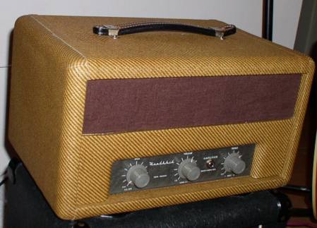
    I just got a Heathkit A-7E, and the build (circa 195?) was so horrific I had to gut it. I tried to mod an old Bell 2122-C hi-fi a bit ago, got in over my head, and made a mess. I figure I'll go back and fix it when I know more about circuit design and have polished my soldering skills. Anyway, I thought that was ugly, till I turned this A-7 over and looked at the wiring job! I'll bet it never worked, and possibly killed the guy who first plugged it in!

    So I'm down to a couple trannies and some solid tube sockets. It's got 12V heater taps, and all octal sockets, and I'm thinking of building something based on an early Fender Deluxe design (push-pull, 5y3 rectifier). I know they used 6.3V heater tubes (6SC7s, 6SL7s, 6V6s). I'm not really trying to copy a Fender circuit, just use a similar tube complement/layout/circuit plan.

    So here are my questions for you guys:
    how hard is it to get the 12V equivalents to those tubes?
    Are they around? NOS only?
    Are they actually equivalents to the 6.3V tubes (in terms of plate voltages, current and etc.)?

    And-- how far would you need to deviate from this schematic to create an amp that does right by electric guitar? I assume I'll need a different tone stack (maybe a fixed mid). In terms of tone, I am open to different sounds, but want to be able to push into sweet distortion.

    What would you do to this, given the trannies I have, the 12V needs, and the octal sockets I'd like to keep?


    Here's a link to the A-7E schematic on the Audiophool site: http://www.audiophool.cjb.net/Schem_A/Heath_A7.gif

    Thanks in advance for any suggestions!

    --colin

  • #2
    You can wire any two tubes with 6.3vac filaments in series and run them on 12vac.
    The filaments would be like two nearly same resistors in series, so the 12v voltage will be roughly divided evenly at around 6v for each tube.
    But truthfully those 12v tubes are easy to find in NOS and I would just use them and build your own version of a tweed 5C5 type amp.
    Bruce

    Mission Amps
    Denver, CO. 80022
    www.missionamps.com
    303-955-2412

    Comment


    • #3
      Thanks, Bruce. I guess I'll keep it easy and use the 12V tubes. The output tubes were originally 12A6s. Would it be worth using those for a guitar amp? What would be a useful replacement? The OPT has a pair of taps to feed current to the plates on those, and I don't know the voltage (250V would be the max on those, right?)-- so I am guessing if I use different tubes there, I'll need ones that use roughly the same plate voltage? Or am I misunderstanding the situation there . . .

      I did look at the 5C5, actually, as a model. I don't need/want 2 channels, though, so I was thinking of using the extra preamp tube to build a couple extra gain stages. Is that worth doing on a relatively low-powered amp like this? Or will I have unusable amounts of gain if I do?

      Thanks for your tips! I keep realizing the number of holes in my knowledge about tube circuit design (okay, about the entire world of electricity). . . but slowly I'm filling them in.

      --Colin

      Comment


      • #4
        Originally posted by G-hoppa View Post
        Thanks, Bruce. I guess I'll keep it easy and use the 12V tubes. The output tubes were originally 12A6s. Would it be worth using those for a guitar amp? What would be a useful replacement? The OPT has a pair of taps to feed current to the plates on those, and I don't know the voltage (250V would be the max on those, right?)-- so I am guessing if I use different tubes there, I'll need ones that use roughly the same plate voltage? Or am I misunderstanding the situation there . . .

        I did look at the 5C5, actually, as a model. I don't need/want 2 channels, though, so I was thinking of using the extra preamp tube to build a couple extra gain stages. Is that worth doing on a relatively low-powered amp like this? Or will I have unusable amounts of gain if I do?

        Thanks for your tips! I keep realizing the number of holes in my knowledge about tube circuit design (okay, about the entire world of electricity). . . but slowly I'm filling them in.

        --Colin
        I wouldn't get too carried away with unneeded or possibly complex gain stages and all that until you can decide if you can really do this.

        I'd build a lower power version of a 5B4, 5C5 or 5C3 (etc) now and try and rewire the power tube sockets for a pair of 6V6s, but run their two filament leads in series at 12v. You can parallel the two gain stages for a little 3dB boost if you want but you'll probably like it stock for while, I think.
        The power tranny you have is heavy enough for the two Push Pull 12A6s to be around 10-12 watts or so in soft Class A to Class Ab so I think a pair of 6V6s in class AB1 at around 400vdc ought to be fine for now. You might need to use a 360 ohm or higher cathode biasing resistor for the two 6V6 power tubes.
        I'd be surprised if you didn't get and easy 12 watts RMS out of it.
        Your OT might be around 6K to 8K now so it should be OK to.
        Later you can redo it with a tweed 5F6 Bassman type topology and keep the 6V6s.
        Bruce

        Mission Amps
        Denver, CO. 80022
        www.missionamps.com
        303-955-2412

        Comment


        • #5
          Great tips-- thanks. Time to figure out a plan of attack. Tweak that 5C5 schematic first, I guess. I'll post back with news . . . and more questions, no doubt. Thanks for your quick and thorough responses!

          Comment


          • #6
            Originally posted by G-hoppa View Post
            Great tips-- thanks. Time to figure out a plan of attack. Tweak that 5C5 schematic first, I guess. I'll post back with news . . . and more questions, no doubt. Thanks for your quick and thorough responses!
            NO problem. I enjoy it or I wouldn't be here.
            Bruce

            Mission Amps
            Denver, CO. 80022
            www.missionamps.com
            303-955-2412

            Comment


            • #7
              follow-up rectifier question

              Since I'm going to be building a 5C5, which calls for a different rectifier than this originally was built with, I'm assuming I'll need to use the rectifier the 5C5 uses (5U4 or soomething). Can I assume this will not be a problem when paired with a PT that was originally feeding current to a 5Y3? Is the only thing to worry about for rectifier choice the tubes on the output end-- the destination for the B+?

              Thanks
              Last edited by G-hoppa; 04-06-2008, 10:42 PM.

              Comment


              • #8
                One of my first amp builds was converting a Heathkit A7E into a guitar amp. The 12A6's have about 7-10 watts.
                Heathkits were kit amps, so the builds varied greatly. Mine was very neat and had excellent coupling caps.

                There's a bunch of sound clips on my web page
                http://www.naturdoctor.com/Chapters/Amps/Retro.html

                I put the A7E into a tweed head
                See the birth of a 2-watt tube guitar amp - the "Dyno Tweed"
                http://www.naturdoctor.com/Chapters/Amps/DynoTweed.html

                Comment


                • #9
                  PRNDL-- that does sound great. Beautiful tweed cabinet, too! So the only mods you made were to the tone stack? Did you keep the two-channel configuration?

                  I've been planning to put a pair of 6V6s in mine, but you are maybe changing my mind . . .

                  Comment


                  • #10
                    I changed the tone stack and made it into a two channel amp using the push-pull pot (I put in a new one). The second channel has a bit more gain. Also, the input was changed by removing the RIAA circuit and 68K/1M pots on the input jack, which is now on the front panel.

                    There's a difference in plate resistance between the 6V6 (5K) and 12A6 (8K), plus an increase in wattage, which may be problematic.

                    12A6's are pretty cool tubes - inexpensive, and usually built to military specs.
                    See the birth of a 2-watt tube guitar amp - the "Dyno Tweed"
                    http://www.naturdoctor.com/Chapters/Amps/DynoTweed.html

                    Comment


                    • #11
                      PRNDL-- what components on the A-7 constitute the RIAA ciruit? Beginner question, I know.

                      I think I'm going to backtrack on my earlier plan to create a Fender 5C5 on this chassis, and rebuild the A-7 to original circuits (except the few changes you've noted). I think it might be just as instructive for me, and less likely to end up a mess. Besides, I was impressed witht the range of useful tones you were able to get from the original tube complement.

                      Thanks

                      Comment


                      • #12
                        Great looking head box PRNDL !!! You don't see many tweed cabinets with that big radius on the corners.

                        I found a schematic if anybody is interested:

                        http://www.audiophool.cjb.net/Schem_A/Heath_A7.gif

                        There might be a problem with the 5U4 drawing 3 amps on the heater supply, the 5Y3 only needed 2. You could try a GZ34 if a 5Y3 won't do the job but I think you should try the 5Y3 first.
                        WARNING! Musical Instrument amplifiers contain lethal voltages and can retain them even when unplugged. Refer service to qualified personnel.
                        REMEMBER: Everybody knows that smokin' ain't allowed in school !

                        Comment


                        • #13
                          pics of a well-done ground buss out there?

                          Aha-- I wondered about the rectifier. Thanks Loudthud. Yeah-- I will for now stick to the original A-7E plan. 5Y3 it is. Just ordered the tubes-- couldn't find anyone who would match a pair of the 12A6 power tubes, though.

                          In the meantime, anyone out there have a nice photo of a ground buss in place? My last project was a grounding nightmare, and since I have this chassis stripped to the sockets, I might as well try another approach. I know opinions are strong on grounding-- star vs., well, whatever else people do. I'm intrigued by the single copper wire running the length of the chassis--sounds clean and easy to understand (important to me!). But I want to see what it actually looks like in place, and how/where people have mounted it.

                          Thanks

                          Comment


                          • #14
                            One thing that frequently causes problems with grounding is the extra chassis connections at the input and output jacks, and possibly at the filter cap can. Without knowing these things, it would hard to predict what will work. It would be best to have individual caps in the power supply and jacks that don't automatically make connection to the chassis. You are wise to try to plan this out before construction. I can only assume the original was built on terminal strips. Can you post a picture of the inside of the amp?
                            WARNING! Musical Instrument amplifiers contain lethal voltages and can retain them even when unplugged. Refer service to qualified personnel.
                            REMEMBER: Everybody knows that smokin' ain't allowed in school !

                            Comment


                            • #15
                              Well, I didn't take pics before I gutted it. There are some rust spots inside, and I figured I'd strip it all out and treat those, since the hammered finish on the outside is so nice. But I removed literally everything. Pics won't help.

                              It did have terminal strips, which I kept.
                              I'll be using new filter caps, so the can will be there but not connected to anything. It is mounted on an insulating wafer.
                              I'll use self-grounding input/output jacks that are insulated from the chassis, so that should solve the problems you mention.

                              one original input jack was mounted to ground to the chassis, and had a soldering connection for grounding that circuit to the chassis right there. Am I right to think that this point is a common place to ground a buss to the chassis? or should the point of contact for that buss be down by the power cable's 3rd wire grounding point? (I'm assuming that the point of the buss is to have only one contact with the chassis, so all ground traffic flows there, like a stretched out star grounding scheme-- am I right?)

                              Thanks for your help

                              Comment

                              Working...
                              X