To put a period on this project, I did some checking and couldn't spot the problem. Fortunately, I have a great tech in town and dropped it by his shop. Sam (Samamp) spotted the grounding error quickly and brought the amp to life. He also worked out a better grounding scheme and the Super is dead quiet.
Thanks for all the help, guys. I learned a great deal in the course of the project and your assistance was invaluable!
After rewiring the grids, I put tubes in the amp and fired her up. No smoke, no smell... and no sound. I'm going to run back through the solder joints, re-check the wiring, swap tubes, and then print a voltage chart. A quick check revealed very high voltage on the plates of the preamp tubes.
Thanks Bruce. It's an old thread that I revived after setting the amp aside for a few months to work on some other projects. I'll make sure to test as you described. If a new transformer is needed, I'll know what to get.
Before you test this amp with all the tubes installed... (nobody can really help with voltages unless the tubes are all installed).... make sure you set the level of your negative bias voltage (you said it would be adjustable), to the deepest negative voltage the pot will allow.
I know this is an old thread but that "unloaded" 400vdc mentioned previously with no tubes is going to end up being pretty low for this amp unless there is a wiring error, test error or there is something I missed.
You still might be buying a new power transformer and the Weber 798 is good enough for this project.
Voltages will drop down when the tubes are installed. The voltages you see on schematics are only valid when all tubes are installed and the standby switch is in the play mode.
Standby was on when I first tested. I can't remember if I measured again with it off. What concerned me was getting 400+v at pin 6 on the preamp tubes. I'll double check and then pop some tubes in and measure again. Thanks for the response!
Was the standby switch on or off when you made the first measurement? Most meters give an average measurement. When there is no filter cap connected, the output of the rectifier looks like an average of about 280V, the peaks are about 400V, that's what the caps charge up to. What you are seeing is prefectly normal.
I've been working on this build and started testing the completed amp prior to installing the tubes. Everything looked pretty fair with only a couple of voltages that were slightly out of whack in the preamp tubes.
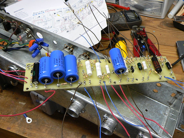
My next step was to install the Weber Copper Cap in place of the 5U4G tube and test without any other tubes installed. I've never used a Copper Cap before, and chose it because the Ballentine PT doesn't have 5v leads. Referencing the Ceriatone layout, I have three wires running to the rectifier at pins 4, 6, and 8-the two reds from the PT at 4&6, and the connection from pin 8 to standby.
Prior to installing the cap, my voltage at pin 8 on the rectifier was 253v. After installing the cap, it jumps to over 400 and feeds that voltage down the line to the preamp tube sockets. I've researched the Copper Caps, but haven't found an answer as to how to tame the voltage or whether I've mis-wired something. I'd appreciate your thoughts on this.
Hey Bruce, thanks for responding. The choke is a Weber/Heyboer unit, Choke for Tweed Fenders. 5-8H @ 200ma, 125 ohm. As noted above, the PT and OT are old Ballantine units from a theater amp, and I'm unsure of the impedance and how to check it. What should the proper impedance be?
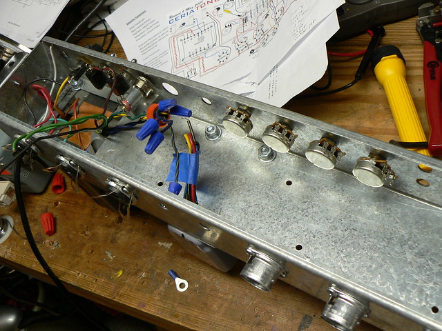
Wow, that's is really an ugly chassis... does it have a faceplate too? It must.
The proper high current choke filter system on these vintage of Fender clone amps is actually a "Brute Force" PI filter.... not a choke input filter. You'll need around 5Hy @ 200ma for it to work right.
Yes, the screen voltage will be higher then the plate voltage on the power tubes...and it's not that big of a deal as the NET gurus will demand it is.
As recommended, use a 470ohm to 1Kohm 2 watt screen resistors on the sockets like the Fender black face/silver face 6L6 amps have had.
Also, like many guys selling tweed "clone" kits (and I use the term "clone" very loosely) they are going the least expensive way with "over the counter parts". The 4k output tranny is the wrong impedance for a true 5F4. Seems like many vendors are trying to use the black face and silver face Pro Reverb/Bandmaster/Vibrolux Reverb OT for those amps.... it works OK but it's wrong and the real amps idled their power tubes at like 45ma to 55ma each.
Not sure if these reissue black face and silver face OTs were made to have that kind of DC idle current in them. MagComp makes really good iron though.

Leave a comment: