Announcement

Collapse
No announcement yet.

6G3 Filtering

Collapse
X
 
  • Filter
  • Time
  • Show
Clear All
new posts

  • 6G3 Filtering

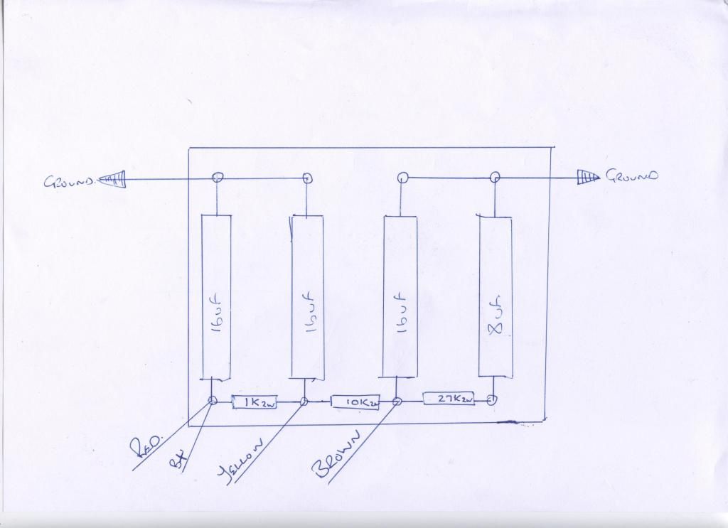
    Have decided to build the 6g3 brown deluxe and as a bit of an noobie to amp building have come across a problem of understanding the fender layout and schematic,on the layout the doghouse isn't on it and cant get my head around the caps and there layout, yep I no they are on the schematic but cant really decipher it,can somebody please explain it or even better if you have a layout of the doghouse.

    Regards

  • #2
    Had another go at understanding the schematic and came up with this--

    [IMG][/IMG]


    Hope somebody can have a look and see if things need moving.

    regards
    Attached Files

    Comment


    • #3
      That looks right. I'm not sure the standard Fender grounding scheme for the doghouse, where the grounds end up terminating.
      Someone else here should be able to comment on that.
      Originally posted by Enzo
      I have a sign in my shop that says, "Never think up reasons not to check something."


      Comment


      • #4
        You left out the wire from the 8uf, the 270v node, which comes through the other hole over behind the volume control for the NORMAL channel.
        Education is what you're left with after you have forgotten what you have learned.

        Comment


        • #5
          Thank you for your help Gents

          Comment


          • #6
            strat100,
            Click image for larger version

Name:	1962 6G3A Deluxe - 298.JPG
Views:	1
Size:	95.4 KB
ID:	835095Click image for larger version

Name:	1962 6G3A Deluxe - 297.JPG
Views:	1
Size:	39.1 KB
ID:	835094
            In support of your project I have attached photos of a 1962 Brown Deluxe doghouse and cap board. As the years go by it's becoming much less likely to see the old amps in original condition. I took the photos before doing any work on the amp and it appeared to be in original stock condition. You can make out all the wires connected to the filter cap eyelet board except for the jumpers between the negative cap leads which are on the underside of the board.

            As an admitted noobie I’m not sure if you are aware of the many discussions about how the less than ideal characteristics of the Fender ground scheme compared to higher construction standards. I’m not trying to complicate your project. Just letting you know. In a nutshell, the original Fender grounding methods were “good enough”, for the low gain amp designs of the day. If your goal is to build a 6G3 Deluxe clone then the original wiring scheme will be fine.

            Tom

            Comment

            Working...
            X