 Tweet
Tweet
Or use a 4k7 resistor and wire the presence up JCM800 style, which actually uses a 25k pot https://el34world.com/charts/Schemat...ead_series.pdf
-
My band:- http://www.youtube.com/user/RedwingBand -
Yes.
Now my self assigned job here is over, I only chimed in because of impossible votage readings, with remeasuring demands offering even more different ones, and with the potentially deadly issue of a winding to core short.
So I suggested a series of (many of them repeated, just backwards for verification) obsessive (veramente rompicoglioni) measurements, step by step.
Now I know the transformer is fine, and you have all basic needed voltages in place, so now you can plug straight into mains and go on with normal procedure.
In any case, I strongly suggest you forget any mods, build amplifier straight like the original Leo Fender way, and follow *his* layout.
The best amplifier in History simply can not be "improved", period:
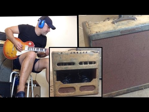
notice the HUGE variation in tone, from sweet to rabid, just varying pick pressure.
He does not touch an amplifier knob once set to play any and all Rock classics.Juan Manuel FaheyComment
-
Very sincerely, I tell you that I greatly appreciate your precious help. You say you have been obsessive. Well, this taught me things I did not know, as well as having established that the transformer works. If everyone was "rompicoglioni" like you the world would be better. Thank you, thank you so much.Originally posted by J M Fahey View Post
Now I'll go with normal procedure hoping you do not disappear from my post.Comment
-
I agree, I thought the same thing. I will update you tomorrow.Originally posted by Helmholtz View PostComment
-
Ok, I put a 4.7K resistor in parallel with the 25K presence pot. I have two 8 Ohm Jensen speakers connected in series, so I change the NFB resistor from 27K to 56K.
Let me know what do you think.
Also, I improved bias wiring with a small proto board. I have two 50K trimmers that set the bias for each power tube.
I turned on the amp without lamp limiter. There is not hum ground. I set the bias, measuring the voltage drop across 1 Ohm resistors from cathode power tubes and ground, to 30 mA. Is it right?
The amp has only a hiss/breathe affected by volume control. Is it normal or should it be silent?Comment
-
So you are using an OT with a 16 Ohm secondary? Just asking as the original is 2 Ohm.I have two 8 Ohm Jensen speakers connected in series
With a 56k NFB resistor, the resistor in parallel with the 25k pot should be 5.6k. The target value for the effective cathode resistance is 4.2k. It results from the parallel resistance of pot value, additional parallel resistor and NFB resistor.
The achieve the exact NFB/gain conditions as in the original BM, the NFB resistor should be 82k, when connected to a 16 Ohm output.
But this not mandatory.
Would you mind to post an updated voltage chart without bulb limiter?
I am also curious about the AC voltage values.Last edited by Helmholtz; 12-17-2018, 02:04 PM.- Own Opinions Only -Comment
-
AC voltage at PT is 642VACOriginally posted by Helmholtz View Post
Yes, my OT have 4,8 and 16 Ohm secondary.
While I was measuring V3 pin 3 and 8 I heard a strong pop after I took off the probe from the pins and amp for a few seconds stopped working, it was silent. I think there is some problem.Attached FilesComment
-
-
Yes, if you are NOT using the presence wiring a la Marshall.So, should I replace the 4.7k with 5.6K?
Please retighten all 4 PT mounting screws/nuts and measure AC voltages from the 2 connected red secondary wires to ground. Are they symmetrical, i.e. about 320V each?AC voltage at PT is 642VAC
Does it work again?While I was measuring V3 pin 3 and 8 I heard a strong pop after I took off the probe from the pins and amp for a few seconds stopped working, it was silent.- Own Opinions Only -Comment
-
Comment
-
We need to know the plate voltage in addition to the current to answer that. This is so the plate dissipation can be calculated.Originally posted by vinceg View PostKeep learning. Never give up.Comment
-
I attached a picture with voltages above. It is 413V, so plate dissipation should be 13.7W, are I right?Originally posted by Reader View PostComment
-
I get 413x.030=12.39WOriginally posted by vinceg View Post
The total actually includes screen dissipation but it is usual to not adjust for that. The 12.39W will be considered a little low by many people but it is a safe value and if the amp sounds good to you then it is OK. IMO there is no reason to use the 70% figures that internet posters mysteriouly worship.Keep learning. Never give up.Comment
-
I agree. I prefer a colder bias. However I'm worried about the 42,5V at V3 cathode. They seem too high, and then there's that question of pop when I measured them.Originally posted by Reader View PostComment
-
There may still be a mistake in the phase inverter tail wiring where the presence circuit is. Extra elevation there would cause higher voltage."Take two placebos, works twice as well." Enzo
"Now get off my lawn with your silicooties and boom-chucka speakers and computers masquerading as amplifiers" Justin Thomas
"If you're not interested in opinions and the experience of others, why even start a thread?
You can't just expect consent." HelmholtzComment
Comment