Ad Widget

Collapse

Announcement

Collapse
No announcement yet.

GT120 project that needs a helping hand

Collapse
X
 
  • Filter
  • Time
  • Show
Clear All
new posts

  • GT120 project that needs a helping hand

    So I've run into a few problems while completing a Hilbish GT120 kit - trying to get some input from some experienced people and was told this is where to come!
    Here is the run down:

    Just prior flying to see the family for Christmas, I 'completed' the amp with hours to spare before my flight, so I tested it and found some smoke and the mains fuse blown - I can't discern where the smoke actually came from (as there were no burn marks) but the only thing that was hot was the choke. I decided to leave it be and deal with it when I came back.

    I initially had a 3-way DPST switch that was off-standby-on and was getting everything to power up fine without the pilot lamp installed, however it was dead quiet (no sound at all). So I decided to swap the switch for what the original GT120s had, which was a 2-way DPST (on-off). I connected the pilot lamp between the Live side of the mains switch and the fuse. When switched to the on position, the pilot light comes on, but nothing else fires up. I haven't changed any of the wiring and am running at 240v.

    I understand this isn't a lot of information to begin with, but I would appreciate any help and direction to getting this fired up safely for the first time and can provide voltages and schems if prompted.

    Thank you in advance!

  • #2
    I'm getting 520vdc on one filter cap and 265ish on the other.
    520vdc on the plates.

    Upon removing the pilot light from the main switch, the tubes do in fact light up, but not very hot.

    Comment


    • #3
      How about posting the schematic?

      I would question exactly how you have the lamp wired up.
      'between the mains & the fuse' sounds odd.
      I would think across the B+ node to ground would be the way to go.

      Comment


      • #4
        In the schematic below, you can see that it reads "use here if a 220v indicator is used" between the mains switch and the mains fuse.
        This however, is not the issue for the lack of sound, as when the indicator is bypassed, I can see the heaters are firing up but there is still no sound.
        This neon has a resistor inside - does the orientation matter? As I was under the impression that it didn't.

        *I found that I had to open the image in a new tab to view the values at a reasonable size*
        Last edited by tboy; 02-02-2015, 09:42 PM. Reason: Incorrect schematic removed. See end of thread for correct schematic.

        Comment


        • #5
          The orientation of the neon should not matter. The problem, if I read the schematic correctly, is that the mains current path is through the indicator. This is wrong. The indicator should be parallel to the mains after the switch as should the transformer primary. Power should not have to go through the indicator to get to the transformer primary. I believe the schematic is drawn incorrectly.

          Edit: "AC In" redrawn as it should be.

          Click image for larger version

Name:	AC-In.jpg
Views:	1
Size:	57.7 KB
ID:	836349
          Last edited by The Dude; 01-02-2015, 11:53 PM.
          "I took a photo of my ohm meter... It didn't help." Enzo 8/20/22

          Comment


          • #6
            I'll give it a go right now!

            *EDIT* So you were 100% right and I'm embarrassed that I didn't catch it myself. Still however, no sound!
            Thanks Duder!
            Last edited by quiettimer; 01-03-2015, 12:05 AM.

            Comment


            • #7
              If you are having initial build startup issues, the best place to start is at the power supply.
              With all tubes removed what voltage do you have at point A & B?
              What heater voltage do you have? (check this right at the transformer leads & then again at all of the tube bases.)
              It appears that there are two separate windings for the heaters, so check them both.
              6.3 Volts/ ac.

              If all is well, insert the preamp tubes & measure the Volts/ dc at the plate pins & the cathode pins.

              If all of these points check you can insert a signal into the input jack.
              No output tubes as yet.
              With all of the controls 'dimed' you should read a very healthy Volts/ ac signal at each output tube grid.

              Comment


              • #8
                ^^^^^^ What Jazz said. You may also want to build a light bulb limiter to save yourself some grief until you get everything up and running correctly.
                "I took a photo of my ohm meter... It didn't help." Enzo 8/20/22

                Comment


                • #9
                  0V at B+
                  529V at A+
                  Heater voltage is 0V
                  Plate voltage is 529V..
                  |It's now starting to be very apparent that something is fundamentally wrong as I check voltages.

                  Comment


                  • #10
                    If you have A+ and not B+, either the 1A fuse or choke is open, or you have a connection problem. Note that the heater voltage is AC and measure across the windings. Did you have your meter set to AC?
                    "I took a photo of my ohm meter... It didn't help." Enzo 8/20/22

                    Comment


                    • #11
                      Crappy project, crappy schematic, the one who drew it has no clue.

                      1) drew the pilot lamp in series with mains voltage.
                      or
                      2) the alternative, showing the pilot lamp in parallel with 6.3V filaments also shows no clue.
                      Unless he specs a "neon " lamp (what's written there) which turns on with 6.3V , that is.

                      Just another would be entrepreneur who got a schematic from the Internet and threw a kit together to get a few $$$$$$
                      Juan Manuel Fahey

                      Comment


                      • #12
                        From my understanding he has an original GT120 that has served as the tracing unit and from what I can tell, the two are identical.
                        Some aspects on the schematic and layout are unclear but that is ok as it's about 95% perfect.

                        Comment


                        • #13
                          Originally posted by J M Fahey View Post
                          pilot lamp in series with mains voltage.
                          Each amp is supplied with its own MEF-approved light bulb limiter. Ya can't go wrong!
                          This isn't the future I signed up for.

                          Comment


                          • #14
                            So I've been able to discern that the choke is what blew - whilst I wait for a replacement from mercury I'm going to use a 1k resistor for the time being and then reinstall the choke.

                            Comment


                            • #15
                              With due respect, 95% accurate is not enough, if 5% errors are gross:

                              1) series pilot light

                              2) fuse suggestion:
                              Says: "5A on 118V ; 3A elsewhere"
                              Must say: "5A on 118 and 110V ; 3A on 220/240V"

                              3) the bias diode is shown the wrong way.
                              That alone is amp killing.

                              4) Power Tube plates are all in parallel, wrongly connected to one end of the Output Transformer and to the screen supply .
                              As gross as can be, shows absolutely no clue.

                              5) all screens are in parallel and connected to the other end of the Output Transformer.
                              As gross as can be, shows absolutely no clue. [tm]

                              Oh well .

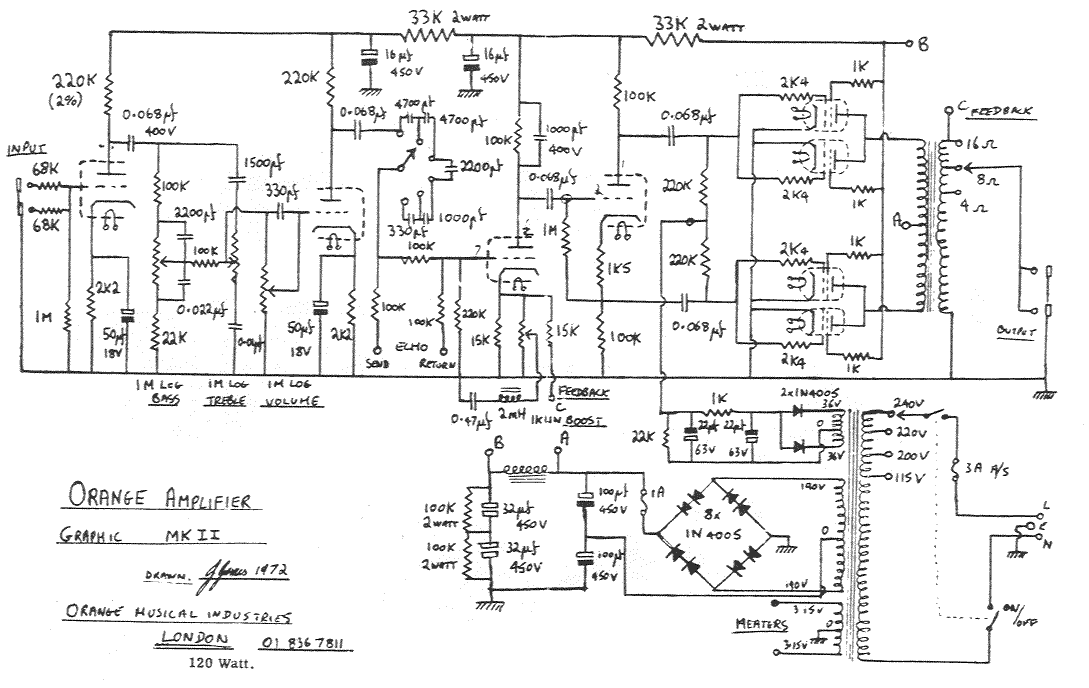
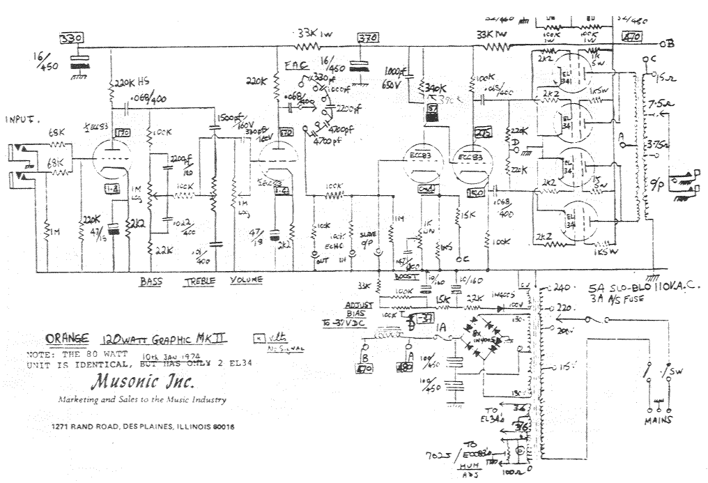
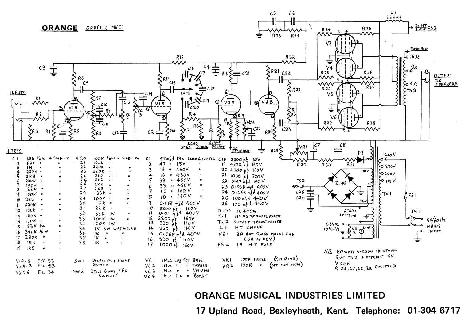
                              EDIT: here's a couple original Orange 120 schematics, I'd suggest you build one of them instead, with small mods to adapt them to the transformers you have.


                              Thanks to orangefieldguide.com , lots of love for Orange and good advice there.


                              WARNING: bridge diodes are incorrectly drawn, check above schematics for the proper connection:

                              Last edited by J M Fahey; 01-03-2015, 03:29 PM.
                              Juan Manuel Fahey

                              Comment

                              Working...
                              X