Ad Widget

Collapse

Announcement

Collapse
No announcement yet.

Power tranny specifications - need help

Collapse
X
 
  • Filter
  • Time
  • Show
Clear All
new posts

  • Power tranny specifications - need help

    I need to have the power tranny of my Silvertone mod. 1482 amp to be rewound.
    The tube complement is:
    6X4
    6AU6
    2x 6V6
    2x 12AX7
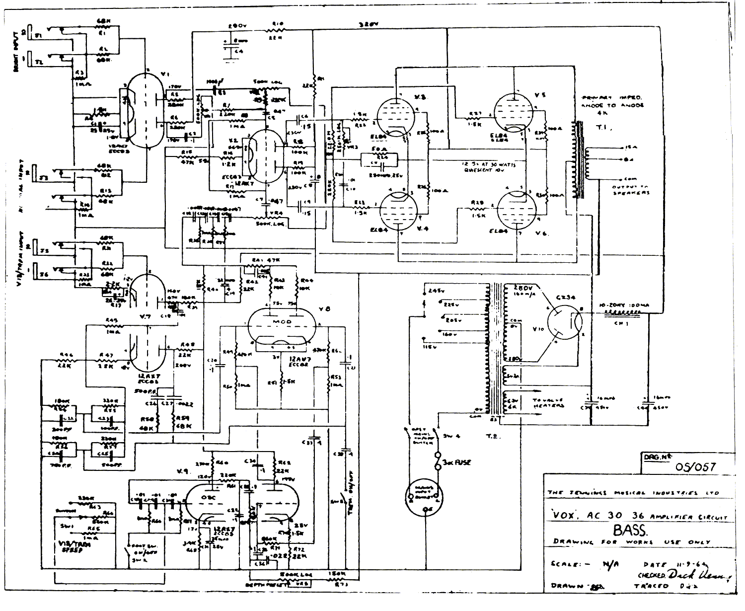
    The HT secondary from the (non-original) schematic attached below is 335-0-335V AC.
    How do I calculate the ampere rating for this tranny? What is the parameter that I have to use (and how do I use it) from the tube specs sheets?
    I need to tell the numbers to the rewind guy.
    TIA
    --Carlo
    Silvertone 1482 #2.pdf
    Carlo Pipitone

  • #2
    For the filaments you can just look up the tube data, add up the current draws, then add 50%. For the HV current an actual knowledge of the current draw may not be as useful. All power supplies sag due to resistance. Some more than others. I'd be inclined to go with a typical rating for a guitar amp with a similar tube compliment. Some research may even reveal an approximation for that particular amp.
    "Take two placebos, works twice as well." Enzo

    "Now get off my lawn with your silicooties and boom-chucka speakers and computers masquerading as amplifiers" Justin Thomas

    "If you're not interested in opinions and the experience of others, why even start a thread?
    You can't just expect consent." Helmholtz

    Comment


    • #3
      6X4 Ih: 0.6A
      6AU6 Ih: 0.3A
      6V6GT Ih: 0.45A
      12AX7 Ih: 0.3A
      Total current draw: 2.4A
      + 50% = 3.6A

      Is that correct? How do I take into account the plate current in each tube?
      Last edited by slidincharlie (Carlo P); 01-09-2015, 09:14 PM.
      Carlo Pipitone

      Comment


      • #4
        For the filaments you can just look up the tube data, add up the current draws, then add 50%.
        +50% on the filament winding is too much. I don't know where you got that from.

        Comment


        • #5
          Uh ...... safety margin?

          Definitely won't hurt.

          Only practical problem is that if rewinding on a previously existing core (vs. a ground up design), available lamination window might not be enough for all that copper.

          Even worse, Silvertones (and all other department store types) were built to a price, so parts rating was "just enough".

          One option would be to supply winder with voltage and current data and let him decide what to do; he will probably use a slightly larger core (I would ; ) which would still fit on that chassis.

          Let me calculate the "just enough" ratings , then if there's room left, he may increase all wire diematers (both filament, HV and primary) by, say, 10% , which gives you 20% margin ... and uses 20% more window space so it might or might not fit.

          I have a gut feeling that only the skinniest of the skinny will fit .

          Post a couple pictures of the transformer, mainly a front one showing available space (if any) between actual winding and iron window.
          And EI lamination size and stack thickness.
          Juan Manuel Fahey

          Comment


          • #6
            Much as I like to keep things original, I think I'd just put an AC15 PT in there and tweak the PS resistors accordingly.

            Comment


            • #7
              Originally posted by Gregg View Post
              +50% on the filament winding is too much. I don't know where you got that from.
              Ok... 50% is a lot. Most filament windings are more like 25% over necessity. You want to keep heat down if you can and you want the winding to survive beyond a fuse in the event of something like a plate to heater short. That's not to mention thermal de rate which is rarely taken into account for such considerations on budget amps because it's an ugly financial consideration. You really don't want your filaments sagging below spec. And I can promise you that if no over rate is applied, they will.

              I'd spec at 3.5A filament winding if possible (as Juan pointed out, there may be limitations).

              Typical PT specs for HV on similar guitar amps (two small bottles) would be between 100mA and 150mA. For that amp I'd probably spec 120mA just to be sure I wasn't too high or too low
              Last edited by Chuck H; 01-10-2015, 01:14 AM.
              "Take two placebos, works twice as well." Enzo

              "Now get off my lawn with your silicooties and boom-chucka speakers and computers masquerading as amplifiers" Justin Thomas

              "If you're not interested in opinions and the experience of others, why even start a thread?
              You can't just expect consent." Helmholtz

              Comment


              • #8
                My only concern about over spec'd heaters is if the 6.3V rises too much when lightly loaded. Otherwise, the only "too much" is that you have to carry it.
                You may also want some leeway for adding more tubes later...
                Originally posted by Enzo
                I have a sign in my shop that says, "Never think up reasons not to check something."


                Comment


                • #9
                  Originally posted by g-one View Post
                  My only concern about over spec'd heaters is if the 6.3V rises too much when lightly loaded. Otherwise, the only "too much" is that you have to carry it.
                  You may also want some leeway for adding more tubes later...
                  Yup. Consider that a popular mod is to swap EL34's into Fender amps that typically run 6L6's. Even most Twin models handle this without trouble. That's more than 3.5A of added current!!! Apparently other designers felt it's a good idea to over spec for safety margin on the filament winding.
                  "Take two placebos, works twice as well." Enzo

                  "Now get off my lawn with your silicooties and boom-chucka speakers and computers masquerading as amplifiers" Justin Thomas

                  "If you're not interested in opinions and the experience of others, why even start a thread?
                  You can't just expect consent." Helmholtz

                  Comment


                  • #10
                    My only concern about over spec'd heaters is if the 6.3V rises too much when lightly loaded.
                    It's actually the other way round

                    Overspec'd does not mean "extra voltage so they have 6.3 under load" but overspec'd diameter/section, which means lower resistance and better regulation.
                    Juan Manuel Fahey

                    Comment


                    • #11
                      It usually means exactly that that's why I was concerned about those extra 50%.

                      Comment


                      • #12
                        Originally posted by J M Fahey View Post
                        Post a couple pictures of the transformer, mainly a front one showing available space (if any) between actual winding and iron window.
                        And EI lamination size and stack thickness.
                        This is the transformer's innards. I do not want to take the paper off before taking it to the winder.
                        What is 'EI lamination size?
                        Is 'stack thickness' the height of the whole stack pf plates?
                        Click image for larger version

Name:	DSC_6955.JPG
Views:	1
Size:	172.7 KB
ID:	836459

                        BTW, I have no intention to add more tubes or swap tube type.
                        Last edited by slidincharlie (Carlo P); 01-10-2015, 07:13 PM.
                        Carlo Pipitone

                        Comment


                        • #13
                          Originally posted by slidincharlie (Carlo P) View Post
                          This is the transformer's innards. I do not want to take the paper off before taking it to the winder.
                          What is 'EI lamination size?
                          Is 'stack thickness' the height of the whole stack pf plates?
                          [ATTACH=CONFIG]32314[/ATTACH]

                          BTW, I have no intention to add more tubes or swap tube type.
                          OK

                          EI refers to lamination shape, wich resemble the letters E and I (duh !!! )


                          I'm interested in 3 dimensions, which let me calculate transformer power handling: "A" (width), "B" (height) and not shown, the individual iron sheets are around 0.35mm thickness each, they are "stacked" to fill the core, I'm interested in that stack thickness.

                          You can easily measure all 3 and I prefer mm rather than In.

                          As of available space, now I see that the grey paper around the wire bobbin touches the outside of the window, so my "bright" idea of adding 5 extra turns to boost just filament voltage won't work.
                          So your rewound transformer will be *almost* the same; only significant difference will be that instead of 2 separate filament windings, say 30 and 31 turns (just made up numbers but to explain how this works) and of say (again, a random number) , 1.5 mm diameter each now you will have a single corrected 6.3V winding with around (6.4V/5.9V)*31=33.6 turns=34 turns , and wound with 1.5*1.4142=2.12 mm diameter wire .

                          In a nutshell: new filament winding will have 8.5% more turns and use 40% larger diameter (2X section) so it will feed all existing tubes and in fact is what the original USA made must have used.

                          Same correction applies to secondary, if needed, and, personal opinion, I'd ask winder for 2 primary taps, a 230V one for use all over Modern Europe and a somewhat lower one, say 215V, to use in small towns where supply might be somewhat poor.

                          What I suggest does not require calculating from the ground up but small corrections, is based on existing winding which, after all, does work, just not too accurately and , most important, practically will use same space.

                          In a way, this makes rewinder work much easier

                          Note: adding the 215V tap is easy and uses no extra space.

                          He just winds until 215V ; scratches wire and solders a piece of wire (215V tap) and continues a few extra turns until 230V , which he was originally committed to do anyway.

                          Nothing new under the Sun, many classic PT had multitaps to work anywhere:

                          just look at this VOX AC30 power transformer, they went as far as to provide selectable taps at:
                          245/225/205VAC meaning 20V "steps" ; of course user would choose the one closest to local real mains voltage.

                          Juan Manuel Fahey

                          Comment


                          • #14
                            Juan
                            here are the three measures:
                            A = 75.3 mm
                            B = 62.8 mm
                            stack = 41.4 mm.

                            The heater windings are 1.1 mm diameter each, as measured at different points of the accessible length of wire.

                            A double primary tap is a nice idea in itself (I am used to my silverface Fender amps, which all have a multi-tapped primary) but I never know the actual voltage at the wall socket in the places wher I play, so I cannot benefit from a 215V tap. As a matter of fact I never change the mains voltage selector in my Fender amps...
                            Carlo Pipitone

                            Comment


                            • #15
                              Originally posted by slidincharlie (Carlo P) View Post
                              Juan
                              here are the three measures:
                              A = 75.3 mm
                              B = 62.8 mm
                              stack = 41.4 mm.

                              The heater windings are 1.1 mm diameter each, as measured at different points of the accessible length of wire.

                              A double primary tap is a nice idea in itself (I am used to my silverface Fender amps, which all have a multi-tapped primary) but I never know the actual voltage at the wall socket in the places wher I play, so I cannot benefit from a 215V tap. As a matter of fact I never change the mains voltage selector in my Fender amps...
                              OK, that core is:
                              * American size #111


                              * very close to European size EI 75 (which is the A dimension in mm)

                              and is good for up to 107 VA tops, in a Commercial product (DIYers are much more generous but have less budgets constraints)

                              Filaments eat 2.4A @ 6.3VAC= 15 VA

                              Minimum acceptable current carrying capacity is 3A/mm^2 so new filament winding needs at least 3/2.4=1.25 mm^2=1.30 mm diameter (16 AWG)

                              Since the old dual 6.3 V winding used 1.1 mm diameter and equivalent single wire is 1.1*1.414=1.55 mm^2 I see it was not improperly designed (the rewinding, that is, can't vouch for original Supro one) , looks like rewinder tried to fit as much wire as possible; pity there was that misunderstanding about offering a 6.3+6.3 winding instead of a thicker single one.

                              So in a nutshell:

                              a) wind filaments for 6.4 V, considering it will always drop a little
                              use 1.5 or 1.6 mm diameter wire, the equivalent of 2 old windings so it will use the same space.
                              To check calculations, said winding should have 8.5% more turns than what it has today (I mean any of the 6.3V windings, not both in series).
                              What I'm writing here seems very dumb and redundant ... but since there has already been a couple miusunderstandings try to triple check everything and make certain both agree.

                              2) HV winding looks roughly correct, use same diameter wire but correct voltage up/down as needed to make that amp happy.

                              3) match primary to wall voltage , use same wire diameter as you have now.

                              4) good luck.
                              Juan Manuel Fahey

                              Comment

                              Working...
                              X