Announcement

Collapse
No announcement yet.

Old Aussie amp problems

Collapse
X
 
  • Filter
  • Time
  • Show
Clear All
new posts

  • Old Aussie amp problems

    G'day guys,

    A few questions for those more learned than me please. (Wasn't sure whether to post here or theory and design)

    I have an old 60s Diason 10w Guitar amp which was given to me in a sorry state to fix. 1 12ax7, 2 6GW8s. The problem is people have obviously been in here playing previously and there are no schematics avail.
    I've drawn one up to use and its baffling in several areas; (sorry it's in 2 parts as I didn't have access to A3 scanner, I will scan on Thursday when back at work)

    Click image for larger version

Name:	Diason baby a4 Schematic_Page_1.jpg
Views:	1
Size:	317.1 KB
ID:	870595

    Click image for larger version

Name:	Diason baby a4 Schematic_Page_2.jpg
Views:	1
Size:	328.4 KB
ID:	870596

    The original tremolo switched off by grounding the trem pot wiper which grounded the o/p of the PI plate. This was causing no end of dramas. I've moved it to gnd the Oscillator cct and it works much better. Amp works ok now but no real oomph.
    It also had no grid stoppers/leak R on one 6gw8. now fitted to match the other. ( thanks to some keen eyes on the Aussie gear heads site)

    My main question was the PI. The 2 output signals are different. The Plate output side is about 1/2 of the cathode o/p. (2V vs 4V)
    The input to the PI grid is fine. Allowing for the way I've drawn it, i don't get how its all connected. Hopefully someone can help?
    If I disconnect the tremolo i/p I lose all the i/p into V2B.

    Also questioning the Plate voltages are high enough?? 125V 12ax7 / 110 osc / 140V PI / 240V on O/P tubes.

    Hope this all makes some sort of sense?

    Cheers and thanks in advance.

    Gavin
    Attached Files
    Cheers,
    Gavin
    ------------------
    Tone, its in your fingers mate!!

  • #2
    Click image for larger version

Name:	6GW8.jpg
Views:	1
Size:	408.9 KB
ID:	841961
    Gavin,
    One thing stands out.
    The 2 x 270K grid leaks for the output pentodes is quite obviously wrong. The 2 x 270Ks (one from each pentode grid [before the grid stops]) should join at their bottom and that join go to the tremlo pot wiper. They might be 220K, I had trouble reading your schematic trace.
    That is not what your trace shows. Check this first.
    Also the grid stops are shown as 220K, these should be say 22K not 220K.

    See my scribble attached for what I yhink it should look like. PM me either here or on the Oz site if you need 6GW8. I have a small stash of them since they are one of my fav. tubes, for HIFi as well as GIT Amps.

    Cheers,
    Ian

    Comment


    • #3
      There are some errors, either drawing mistakes or worse, they are actually there.
      The worst and which must be corrected NOW is that V3b has no reference to ground, as has.
      You also have one 220k resistor connecting PI cathode, which is at relatively high positive voltage above ground, straight to V2b grid, which is impossible.
      In a smaller scale, I bet 220k grid stops will kill all punch out of this amp.

      Please label all resistors, capacitors, pots (R1 - R2 - .... C1 - C2 - ....) so we can refer to them.

      MAYBE the amp is actually as drawn, aftter all "somebody messed with it" , but it can be properly rewired wired.

      These seem to be Goldentone's "second brand" and so some more [popular model should be close by.

      Also replace that horrible halfwave rectifier with a full wave bridge.

      I'm curious about the speaker, is it one of mythical "Australian Rola" ones?
      Juan Manuel Fahey

      Comment


      • #4
        Thanks guys, appreciate the responses.

        Yep that schematic is unfortunately correct. They are all 220k.

        I think yr 100% Ian. The components in there look like they are left from that cct you drew. Someone has bastardised it badly. Also Do you think a grid stopper of say 10k would be OK on the PI input?
        No screen resistors either but other period Oz amps don't seem to have them either.

        I will redraw with the components labeled, good idea Ta.

        No idea re the speaker as I was just given the chassis by post. Will find out.

        Probably good idea to chuck in a bridge rectifier as the voltage does drop down over 10minutes.

        Thx again

        Gavin.
        Cheers,
        Gavin
        ------------------
        Tone, its in your fingers mate!!

        Comment


        • #5
          I suppose you know about the Diason page at OZ Valve Amps ?

          Diason

          To those unaware the 6GW8/ELC86 has a power amp tube and a pre-amp tube in the one glass envelope !
          They were used in B & W TV sets.

          Gavin here's two circuits , one is a Diason the other a Goldentone .The Diasons have an uncanny family resemblance to the Goldentone!
          They are slightly different but ignoring the reverb are a rough guide.

          http://ozvalveamps.org/goldentone/suitcasecctrdw.gif

          http://ozvalveamps.org/diason/diason...it090318dl.gif

          And Juan ..talk about waving a red flag in front of a bull "mythical "Australian Rola" ones" huh? .. I shall return one day with a response!!!

          Comment


          • #6
            Here's a link to some information on Australian current production Lorantz speakers, with a bit of a history lesson farther down the text. A fair bit of information about Aussie Rola speakers contained!

            LORANTZ SPEAKERS ? MELMUSIC - MELBOURNE MUSIC CENTRE

            Comment


            • #7
              Thanks for that interesting link.

              We have a quite similar Industrial history with Australia/New Zealand, including our excellent Electronics Industry being destroyed around 1975 (we also made Ford Falcons )

              PLESSEY ROLA CLOSURE

              As engineering manager I was saddened, disappointed and devastated to witness the closure of the loudspeaker manufacturing division which was an icon in the Australian audio industry. Plessey Rola ceased production of loudspeakers in Australia in 1975. Tariff protection had been significantly reduced ( a common practice today) with the result local manufacture of audio products and customers diminished, car manufactures opted for cheaper imported loudspeakers. Hence the demand for local manufactured speakers diminished making speaker production on the grand scale we were accustomed to was no longer viable. Is it good? Speakers today are much cheaper but it has come at a cost, our jobs.
              And what was Plessey Rola?

              Oh, "almost nothing", the Australian branch of one of the best Electronic companies in the World.

              Just as a sample, not only they made own speaker frames and mechanical parts but own cones and own magnets (yes, mixing and casting own Alnico and mixing and cooking own Ferrites) and making same models as mythical British Celestion from the 50's.


              Australian Rola 1948 G12 speaker ... ring a bell?


              UK Rola Celestion, same era:


              who says tariff is bad and unlimited free commerce is good?
              Juan Manuel Fahey

              Comment


              • #8
                Thanks mate,

                Yep had trolled the Ozvalve amps site for similar schematics and these two are the ones I'd printed out and referred to. Escpecially the goldentone.
                Apparently someone had 'repaired' this amp previously using a maton schematic that was similar.

                I rewired the tremolo i/p to split 2 ways using 220k to the grids of the 6gw8 (as per Ians note and goldentone schematic also removed the standalone grid leaks andfired it up; the amp sounds terrible!!!! lol, although the two i/p waveforms to the 6gw8s are now the same.

                Fitted an 10K grid stopper to I/p of PI and it sounds much better but still a very sick puppy. Ran out of time to do more unfortunately. Will advise when I know more

                As an aside, WRT fitting a bridge rectifier to these old amps, would you fit a bought one or 'build it' from scratch?

                Thanks again for your interest and help, I really appreciate it!!
                Cheers,
                Gavin
                ------------------
                Tone, its in your fingers mate!!

                Comment


                • #9
                  I would fit a bought one as looks neater .

                  While you're there here's an oddball one by Jaret.
                  It's cathode biased .. and as stated on the schematic "modified".
                  Just thought an interesting variation on a theme... this one was by Moody.. haven't found a 6GW8 version before.
                  Usually they had EL34's.
                  Attached Files

                  Comment


                  • #10
                    Thanks mate.
                    That Moody is similar to a (EL34) Vardis (Galaxie) that I have from memory. Haven't finished drawing that one up yet!! It works, so no hurry!!

                    Here is the latest schematic with my changes and component values/labels.
                    Click image for larger version

Name:	Diason Baby Rev1.jpg
Views:	1
Size:	594.8 KB
ID:	841976
                    Cheers,
                    Gavin
                    ------------------
                    Tone, its in your fingers mate!!

                    Comment


                    • #11
                      Hi again,

                      More help for the ignorant please!!??

                      Ive fitted a bridge rectifier and B+ voltage is stable and ok.

                      The biggest problem for me is I'm chasing my tail as I have no idea if this circuit "should work".

                      Bottom line is that wave form is basically ok to i/p of the PI. There is a slight distortion of waveform. Not sure if this is enough to be causing the dramas I have later.....

                      Click image for larger version

Name:	IMG_5141.jpg
Views:	1
Size:	17.5 KB
ID:	842010

                      O/p from Cathode of PI measured at pin 8 grid of V3B is....

                      Click image for larger version

Name:	IMG_5143.jpg
Views:	1
Size:	18.2 KB
ID:	842011Click image for larger version

Name:	IMG_5143.jpg
Views:	1
Size:	18.2 KB
ID:	842011

                      However O/p of PI plate to V2B grid pin 8 is not nice. Bottom is flattened out indicating bias issues? (Duanes guide)...

                      Click image for larger version

Name:	IMG_5144.jpg
Views:	1
Size:	18.3 KB
ID:	842012

                      Plates of output tubes are a dogs breakfast....

                      V2B

                      Click image for larger version

Name:	IMG_5145.jpg
Views:	1
Size:	19.5 KB
ID:	842013


                      V3B

                      Click image for larger version

Name:	IMG_5146.jpg
Views:	1
Size:	19.4 KB
ID:	842014

                      I'm about at the end of my tether (and experience level), but I don't want to let it beat me!!

                      Hopefully someone can help me in the right direction?

                      Thanks Heaps
                      Gav
                      Cheers,
                      Gavin
                      ------------------
                      Tone, its in your fingers mate!!

                      Comment


                      • #12
                        Well it's starting to take shape even if the shapes it makes are a bit wonky !! Maybe the power supply is too efficient !
                        To help with the long distance diagnosis would be a good idea to fill in some voltage readings on your schematic and
                        may I suggest you put in the "voltage per division" along side the cro pics.
                        Perhaps working backwards.. the cathode resistor at the output could be increased but that's putting the cart before the horse!
                        Some voltages please.

                        Comment


                        • #13
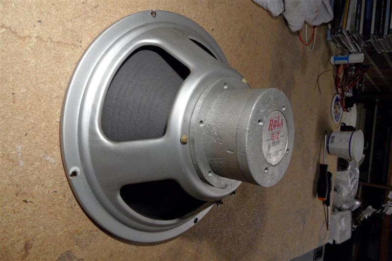
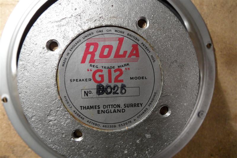
                          Australian Rola 1948 G12 speaker ... ring a bell?


                          I managed to pick up a couple of these very rare speakers from 1948 over the last decade ( at great prices)

                          Click image for larger version  Name:	RolaG12_4.jpg Views:	0 Size:	1.21 MB ID:	928655
                          Click image for larger version  Name:	RolaG12_3.jpg Views:	0 Size:	494.9 KB ID:	928652

                          Click image for larger version  Name:	RolaG12_1.jpg Views:	0 Size:	1.36 MB ID:	928653
                          Last edited by walkman; 04-11-2021, 01:56 AM. Reason: clarity and duplicatrion

                          Comment

                          Working...
                          X