Ad Widget

Collapse

Announcement

Collapse
No announcement yet.

peavey classic 30 reverb driver and recovery issue

Collapse
X
 
  • Filter
  • Time
  • Show
Clear All
new posts

  • #16
    Originally posted by Jazz P Bass View Post
    It appears that you have proved that the circuit works through the pan.

    Up next is the output from U1B/ pin 7.
    After that is C23 & the JFet.
    I would do as suggested & remove Q1 & jumper across pins 2 & 3.

    [ATTACH]50929[/ATTACH]
    I did check this jrc 4558 with a 9volts battery before I installed. they were reading
    pin 1 8v
    pin 2 4.5v
    pin 3 4.5v
    pin 4 9v
    pin 5 4.5v
    pin 6 4.5v
    pin 7 8volts
    pin 8 is 0

    was expecting to see 4.5v for pin 1 and 7, that's how I normally see them inside a pedal wired with other components. but I guess the voltage is different when just the IC and the 9v source?
    Comment


    • #17
      I'm not clear what the C30/R37 network is. It's a moderate load to the Reverb Return circuit amp, but I don't think it's involved in driving Q1. I think Q1 FET is just working as an On/Off device to pass signal back to the main signal, mixing in with the dry signal. Does the delta blues amp also have reverb...pretty much this circuit, or no? If so, then I guess lift it out.

      On the Reverb pot, contact cleaner should be applied...don't need much...enough to get onto the track/wiper and work it in to break down the years of oxidation that has it gritty.
      Logic is an organized way of going wrong with confidence

      Comment


      • #18
        Delta Blues has exact same reverb circuit except all the switching stuff is missing.

        I did check this jrc 4558 with a 9volts battery before I installed. they were reading
        pin 1 8v
        pin 2 4.5v
        pin 3 4.5v
        pin 4 9v
        pin 5 4.5v
        pin 6 4.5v
        pin 7 8volts
        pin 8 is 0

        was expecting to see 4.5v for pin 1 and 7, that's how I normally see them inside a pedal wired with other components. but I guess the voltage is different when just the IC and the 9v source?
        WHATT????

        What is this test supposed to show? You connected the +9 to the negative power pin, and the - end of the battery to the positive pin? Sounds backwards. And with the input pins not terminated, the outputs would then likely slam over to one rail or the other. The whole point of a reference voltage in your pedals and such is to center the voltages. The IC doesn't do it.
        Education is what you're left with after you have forgotten what you have learned.

        Comment


        • #19
          Originally posted by Enzo View Post
          Delta Blues has exact same reverb circuit except all the switching stuff is missing.


          WHATT????

          What is this test supposed to show? You connected the +9 to the negative power pin, and the - end of the battery to the positive pin? Sounds backwards. And with the input pins not terminated, the outputs would then likely slam over to one rail or the other. The whole point of a reference voltage in your pedals and such is to center the voltages. The IC doesn't do it.
          Oops you are correct, I meant pin 8 is 9v and pin4 is 0. Had a bag of these 4558, thought it was a quick test if one particular 4558 in the bag is good

          Anyway got a tank from a blues Jr. Smaller tank But Same 60ohm input and same 200ohm out. Still no go with the classic30. The c30's 4eb2c1b tank works fine with the blues jr. as well as the classic 30 reverb driver circuit As seen here in this vid
          >
          http://youtu.be/dLvrRpmiAGM

          Dry coming out of thr classic 30 and full wet reverb out of the blues jr facing the wall... wow what an awesome effect!

          well definitely it's the recovery or the pot. Still feels like an expedition when going in this amp eventhough I found a way not to stress the jumper by rotating the 3pc pcb, instead of pressing in the pots shaft

          Comment


          • #20
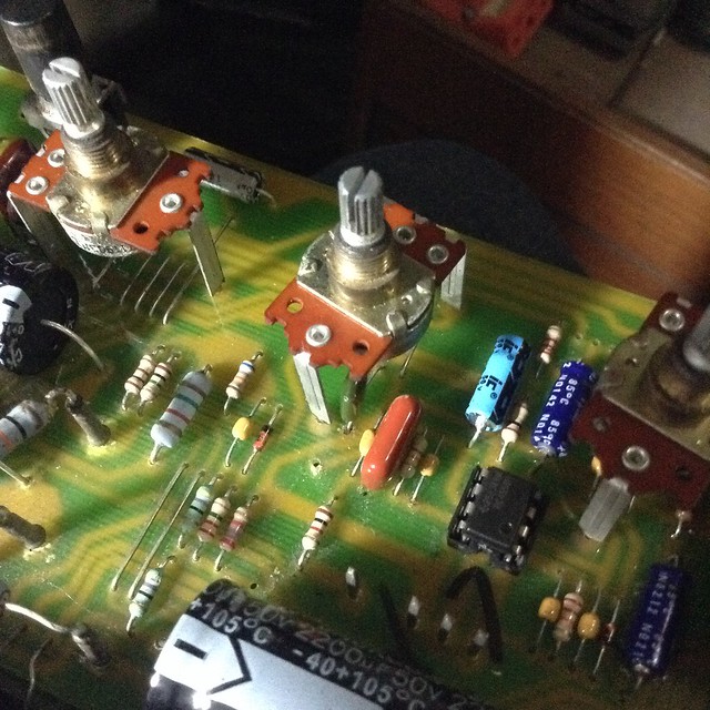
            Managed to open up the amp finally. also found a way to take out the chassis without snagging the tolex... by wedging both sides of the chassis with cut up beer cans.

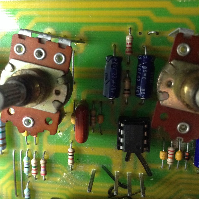
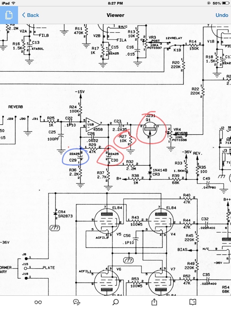
            base from the suggestions above, I plan to take out the red components, Q1, R27 and C30.
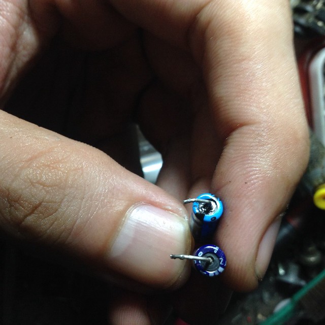
            the blue component C29 says 22uf in the c30 schematic. but in my amp it was actually .47uf IC brand capacitor


            light blue IC component is .47uf, this is the same c29 with Delta Blues reverb, I wonder if it makes a difference?


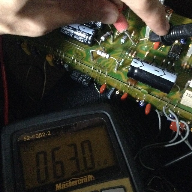
            I wanted to check which component caused the reverb to fail. this cr3 diode has a resistance reading of only 63k ohms


            upon further inspection on the recovery circuit, I checked the c29 and it looks wet. i dont know if it leaked or what, it was still reading .47uf on the capacitance


            well took it out and replaced it with the 22uf from c30, jumpered the Q1 and hoped for the best


            Finally got the reverb back! and that low hz hummm lol
            >>> https://youtu.be/zUWs6x4eZrE

            Thanks everyone! owe you guys! to think I almost hardwired my boss rv3 on this haha.
            fix this up just in time for the halloween party, Happy Halloween everyone!

            Comment

            Working...
            X