Ad Widget

Collapse

Announcement

Collapse
No announcement yet.

Tube amp output impedance

Collapse
X
 
  • Filter
  • Time
  • Show
Clear All
new posts

  • Tube amp output impedance

    I've tried to work out the output impedance of my amps by measuring a clean output signal voltage at open circuit, then loading the output until the voltage halves.
    I kept the signal at such a level that none of the tubes should be shutting off, the reasoning being that cut off may cause inductive spikes that the open circuit secondary would exaserbate; 10Vav for the AC30 and JTM45, 5 V for the 5E3.
    Both JTM45 and AC30 type amps were about 50 ohms on the 8 ohm output, 100 ohms on the 16 ohm output.
    A 5E3 was about twice that (due to the lower screen voltage?, I'll try increasing it to to see if it makes any difference).
    It's just that I'm concerned that the output impedance will increase at higher signal levels, when the tubes cut off for part of the wave, due to the push-pull sides no longer being effectively in parallel.
    So at high signal levels, especially overdriven, the output impedance may be twice (?) as high?
    Pete.
    My band:- http://www.youtube.com/user/RedwingBand

  • #2
    I've tried doing this to a solid state power amp that had that wacky mixed mode feedback. That's where there is a low value resistor in the ground leg of the speaker that senses current in addition to the normal non-inverting opamp type feedback. I set up a spreadsheet so I could just plug the numbers in. I found that I could never get the same number twice. I tried it with an open circuit, 4 and 8 ohm load. I didn't try changing the level of the measurements to see if that made any difference.
    WARNING! Musical Instrument amplifiers contain lethal voltages and can retain them even when unplugged. Refer service to qualified personnel.
    REMEMBER: Everybody knows that smokin' ain't allowed in school !

    Comment


    • #3
      If I understand what you're saying, then your line of thinking essentially describes the mode of operation for all class AB amplifiers. When drawing load lines for stages designed for AB, you plot both A and B load lines. Essentially when one half cuts off (transitioning into class B operation), it sort of 'disappears' from the point of view of the other half, and the impedance halves. This halving of impedance at cut-off is actually pretty useful, as it allows you to curve your load lines around the dissipation limit, or even straight through it.

      For further clarification; when one half cuts off, in addition to no longer being in parallel with the other, the entire half of the primary is no longer part of the circuit.

      edit: confused halved with doubling!
      Last edited by exclamationmark; 02-21-2012, 04:24 PM.

      Comment


      • #4
        Rather than using an open circuit and a 50 ohm resistor why not use 9 ohm and 8 ohm resistors? then you could drive it as hard as you like and have more fun doing the calculations.

        Dave H.

        Comment


        • #5
          'have more fun doing the calculations'
          I'll have fun with the measurements, not the calculations!
          To save my brain hurting, what is the calculation procedure?
          eg if I measure 10V across 8 ohms and 11V across 9 ohms, how do I then derive the output impedance?
          Pete.
          My band:- http://www.youtube.com/user/RedwingBand

          Comment


          • #6
            If you keep changing the load resistor value, from a low value to a higher value, wouldn't you end up with a 'bell curve'?
            The peak would be the most efficient load (ie: speaker dc resistance)
            For the most effective transfer of power, the generator should match the load.

            Comment


            • #7
              A suggestion:

              Adjust the output for a given voltage with no load. Add the dummy load and see how much the voltage drops. The voltage drop is due to the output impedance. Since you know the current (voltage across dummy/resistance), you can calculate the output impedance (current/voltage drop).

              I think pdf64's method loads the output too much.

              Comment


              • #8
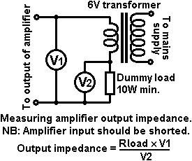
                A classic method:

                Comment


                • #9
                  Originally posted by pdf64 View Post
                  To save my brain hurting, what is the calculation procedure?
                  eg if I measure 10V across 8 ohms and 11V across 9 ohms, how do I then derive the output impedance?
                  Pete.
                  To save your brain I'll not tell you how I derived the equation below ;o)

                  Rout=72(V9-V8)/(9V8-8V9)

                  Where V8 and V9 are the voltages measured across the 8 and 9 ohm resistors. Putting in your numbers gives -

                  72(11-10)/(9x10-8x11)=36ohms

                  When I tried it in simulation on an AC15 I got V8=12.135(peak), V9=13.352(peak) which gives Rout=36.5ohms!
                  A 5E3 sim at 12V gave Rout=66ohms.
                  I then tried it at half the output voltage and got 100ohms for the AC15 Hmm...

                  Dave H.

                  Comment


                  • #10
                    You can't beat the classics...

                    I tried to derive the equation in Merlin's post and came up with:
                    1. Assume the amp output is a perfect coil (the OT secondary) in series with a resistor (the output impedance).
                    2. Then, you have a loop consisting of the 6V secondary, the dummy load (RL), the OT secondary, and the output impedance (RO).
                    3. Assuming a current i flows in the loop, then V2 = i x RL (eq. 1) and V1 = i x RO (eq. 2).
                    4. Rewriting eq.1, i = V2/RL. Substituting this in ea. 2, V1 = V2/RL x RO
                    5. Rearranging, RO = (V1 x RL)/V2.

                    Other thoughts:

                    1. The 6V secondary has DC resistance. I wonder if this should be added to the value to RL.
                    2. The OT secondary also has DC resistance, but it would seem to be part of the output impedance.
                    3. Making the measurement at the mains frequency seems a little odd (or at least incomplete). I would suggest hooking the test transformer up to an amplifier driven by a signal generator and making the measurements at several frequencies. I would guess that the output impedance is frequency dependent, at least in some amps.

                    Cheers

                    Comment


                    • #11
                      I did an experiment one time driving sinewaves into the output of a tube amp with an oversized solid state amp. There were two resistors between the amps so the tube amp saw a 2 ohm load and the solid state amp saw 4 or 8 ohm load. I never calculated the output impedance of the tube amp but, IIRC the low frequencys looked like a 6mH inductor. An impedance that got lower as frequency went lower down to a small resistance at DC.

                      Attached Files
                      WARNING! Musical Instrument amplifiers contain lethal voltages and can retain them even when unplugged. Refer service to qualified personnel.
                      REMEMBER: Everybody knows that smokin' ain't allowed in school !

                      Comment


                      • #12
                        That's right, the output impedance can be a function of frequency because the NFB factor varies with frequency. It can also be a function of output power, because the tubes are non-linear.

                        I personally would measure it by driving the amp at its rated power into a dummy load of the rated impedance. Then connecting an extra load in parallel with the existing one, to lower the impedance a bit. That would drag the output voltage down, and the "before" and "after" voltages could be plugged into the voltage divider equation.

                        For tube guitar amps it would probably be in the range 10-100 ohms, and for tube hi-fi amps 0.5 to 5, but those are massive generalisations.

                        With a solid-state hi-fi amp the impedance is very low, often much less than 0.1 ohms, and quite tricky to measure. You'll trip the protection (or just explode the output stage ) before you can drag the output voltage down by a measurable amount.

                        Merlin's back-driving method comes into its own here, because you can measure the small voltage V1 quite accurately with a sensitive AC voltmeter or even a FFT analyser, rather than looking for a tiny change in a large voltage.
                        "Enzo, I see that you replied parasitic oscillations. Is that a hypothesis? Or is that your amazing metal band I should check out?"

                        Comment


                        • #13
                          'driving the amp at its rated power into a dummy load of the rated impedance. Then connecting an extra load in parallel with the existing one, to lower the impedance a bit... and the "before" and "after" voltages could be plugged into the voltage divider equation'

                          Steve, could you expand on the voltage divider method (for dummies)? As per Dave H's method in post #9?

                          Any thoughts on whether (open loop) output impedance changes significantly between the 'both tubes conducting for full 360 degrees' and the 'one tube cut-off' conditions?

                          Re frequency effects, the method I outlined in the 1st sentence of post #1 gives a result that is consistant over the guitar range (70Hz - 10kHz). I'd expect a guitar OT to be rolling off (at least a little) by 50Hz, eg the Hammond guitar range is -3dB @50Hz.
                          Thanks for everyone's input so far!
                          Pete.
                          My band:- http://www.youtube.com/user/RedwingBand

                          Comment


                          • #14
                            Originally posted by pdf64 View Post
                            Steve, could you expand on the voltage divider method (for dummies)? As per Dave H's method in post #9?
                            Pete, Steve’s method is the same as mine. The ‘potential divider’ is the potential divider formed by the amp’s output impedance (Ro) and the load resistor (RL). Using two load resistors gives you two potential divider equations which can be solved for the amp’s output impedance (and voltage which is assumed to be driving the potential dividers). The equation I posted is the solution for loads of 8 and 9 ohms but you could also use an 8 ohm resistor on the 8 ohm tap and load it down a bit with a parallel resistor as Steve suggested.

                            Dave H.

                            Comment


                            • #15
                              My measure method

                              I use the open circuit output voltage and the voltage into teh standard load impedance as follows.
                              Results will be consistent for an SE amp but can change for a Class AB Push Pull if you are above the Class A to Class AB transition in power output level.
                              Trying to do the measurement above the saturation level will just give rubbish result.

                              Cheers,
                              Ian
                              Attached Files

                              Comment

                              Working...
                              X