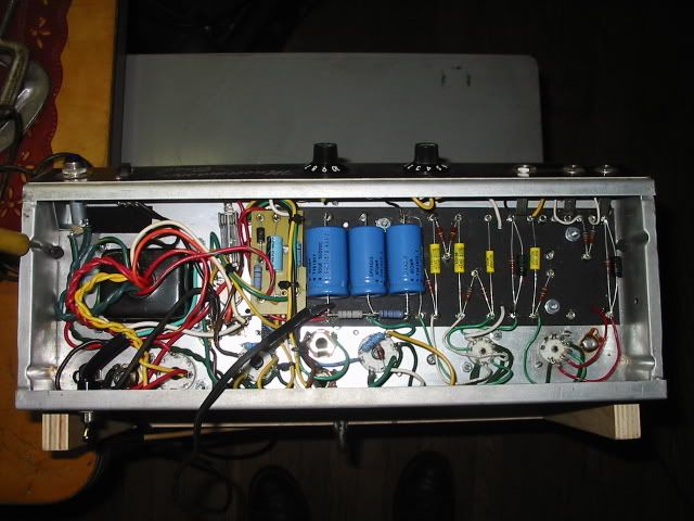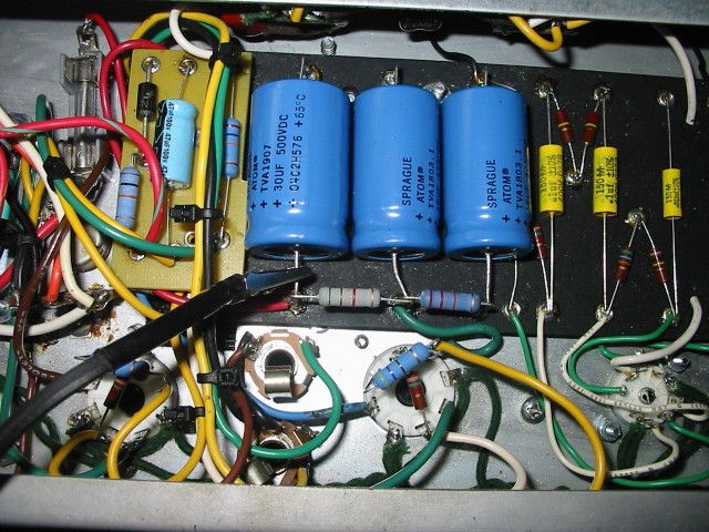
this is the entire chassis .

This is a shot of the amp itself , the bias board that I made is on the left side . This I used in a build I made using a 71 MM bass amp chassis and cab . It is the inputs and tone stack of a fender 6G2 princeton . The preamp is just like a 5E3 as is the PI and power section so V1 is the preamp ,V2 the PI and the rest is the same as a 5E3 other than I added an adj fixed bias. This photo does not show the entire chassis just the area where the 5E3's cathode resister would normally be so to the left is the PT and to the right is the input section of the board which I used weber 5E3 eyelet board and it just fit . the entire circuit was sort of a tight fit and it's worked well for 9 years now.

These are drawings of the way the board is actually setup and one on the left is how my bias board is actually wired. The right showing a more clear setup as fender would use. Basically I used a 50KL pot chassis mounted so I can adjust the bias without removing the chassis . Now what I did was go by what I was told a few years back and wired the pot as I did just in case the pot failed . What I am asking is it really needed to use two legs of the pot as I did which is supposed to well hopefully keep the 27K min in case the pots wiper failed or the wiper contact strip failed. I have seen similar setups on the weber speaker site in his amp kits and also was told this is a better way of doing this. It does work fine as it is wired . I use either 6V6's or 6L6's with this chassis which has beefed up Allen Amps tranny's and the range resister and 50KL pot and 27K resisters allow me to bias either set of tubes . I have never had a problem and did the bias board a dit odd so I could get the three leads to the bias pot neatly since as you can see there is not a lot of room in there , the pot is just to the left of the bias board but down through the chassis.