Announcement

Collapse
No announcement yet.

I Don't Understand Guitar Wiring: Where's the Circuit?

Collapse
X
 
  • Filter
  • Time
  • Show
Clear All
new posts

  • #16
    Thought I'd jump in here.
    You are absolutely correct that there is an "open circuit" in the guitar.
    Until you connect it to an amplifier input jack.
    The amplifier input circuit connects the loop.
    The simplest pickup circuit would be the pickup wires connected directly to the amp input jack.
    No volume control. No tone control.
    Again, the pickup is "open circuit" until it is connected to the amplifier.
    Comment


    • #17
      Steve: It's always comfortable to hear what you wanted to hear in the first place. You've just allowed me to do that and at the same time expressed why I had to see this through. I responded to Sweetfinger's comments before I read your message, and it is interesting to see you put it in terms of the amplifier being the "consumer" and the pickup the "generator", after I made analogy to wiring and using a household lamp, wherein as consumers it is easy for us to forget that if things are not set up for unused power to return to the generator, we aren't going to have any light. Anyway, that question has been answered in a manner that makes sense to me, so it's time to stop beating the dead horse on that one.

      You also got the bigger issue that is looming in the background as more important for me to get a handle on, now that I've been able to put the major circuit issue that was bugging me to to rest. I have been studying schematics of wirings using the super switch and the fender S1 switch and recommended wirings of pickups, and there are just things going to ground all over the place, never mind that the hardware has to be grounded just to be grounded (while I think I understand what you mean to say, "Ground" is a fiction beloved of EEs and techs," I presume that part of the grounding actually represents grounding, and that's part of what makes it hard to sort out what's grounding and what is the negative end of some circuit in the guitar's functional wiring). I also find points where it appears that certain connections in a switch simply connect the same wire of a pickup to itself, and I don't see the point in that.

      Putting that aside, I find I get confused trying to think through even some very simple component set-ups. Joe recommended yesterday that I look at guitar circuits in very simple contexts, in what I presume was meant to be a very simple and enlightening exercise, and I missed the boat entirely, in part because I was looking for completed circuits and I could not allow myself to include the output jack, simply because I could not see it as part of a completed circuit (for reasons already covered ad nauseum). Now that that is put to rest, I went back and reconsidered the same 3 simple set-ups I did yesterday (pickup alone, pickup with volume pot, and pickup with volume and tone pots) but allowed that the jack is, in fact, part of the circuit.

      I think considerations of the isolated single coil pickup and of the single coil pickup with volume control were straightforward, but I am confused regarding the addition of the tone pot. The only circuit I could find that actually connected to the jack did not have any obvious power source. Starting from the tip, it went to the wiper terminal of the volume pot, from there to the end terminal of the volume pot, then to the wiper terminal of the tone pot, then to the end terminal of the tone pot, on through the capacitor and via "ground" to the sleeve. I could not find any way to include the pickup as a power generator, so I did not see what would motivate current to pass through the tone pot and capacitor. Then I found a circuit wherein the current passes from the pickup through the tone pot and capacitor but does not get to the jack, so I was clueless what the point would be in that. I finally put the two together in what looks like a parallel circuit connecting the jack and volume pot through the pickup on one side and the tone pot and capacitor on the other. Plainly this would allow no direct current from the pickup to pass through the tone pot and capacitor, but it leaves me to wonder if the capacitor is not simply seeing the current that makes it through the resistance of the volume cap and acting on that. If I am seeing it correctly, part of the current would be expected to pass through the volume pot unaffected by the tone pot and capacitor, and part would pass through and be affected by the tone pot and capacitor. Perhaps the degree of resistance set on the tone pot determines how much of the current finds its way through that part of the circuit rather than heading back toward the pickup? That seems to make sense. For what it's worth, I've attached all the schematics I created in this exercise.

      One more point that mucks up my thinking here...Someone informed me last evening that current passes from positive to negative. You've reported, instead, that in an AC circuit it alternates direction. I guess that's obvious, but it really makes it difficult to see how these components act as filters. When I look at the drawings where the current runs from positive to negative, ironically, even in the simple case of the pickup alone with volume pot, it appears that the volume pot is, in fact, acting on the current returning from the amplifier! If you reverse the flow to go from negative to positive, it appears to more naturally have the volume pot acting on the signal on its way from the pickup to the amp. But then, when you add the tone pot, it gets crazier. Again, if you consider current moving from positive to negative, the tone pot and capacitor are seeing the current after its passed through the volume pot on its way back from the amplifier. On the other hand, if you consider current moving from negative to positive (just reverse the direction of the arrows on my drawing in your head), you still have power returning to the capacitor and tone pot on its way to the volume pot, while current is headed in the other direction to be augmented by the pickup. The current that's passed through and been increased by the pickup meets the current that's passed through the capacitor and tone pot at the end terminal of the volume pot, from where it passes through the wiper of the volume pot and on to the amp through the tip. In that case, again, the capacitor is influencing only a very weak current returning from the amp. If you consider that the higher power generated by the pickup might cause current to run backward through the tone pot and capacitor, then that can only go on to the sleeve, and you've got power going in two directions on the one line. I know that power moves cyclically in alternating directions with AC current, but I don't think that makes this Kosher.

      Before I looked closely at these circuits, I thought it all looked simple...the pickup generates power, it goes through the volume pot, then it goes through the tone pot, and then it goes to the amp where it's amplified to produce an audible sound. Now that I've looked closer, it doesn't even look like in that simple case it's all that simple. What am I missing?

      Thanks Rob R
      Attached Files

      Comment


      • #18
        It will help if you get into the habit of reading/drawing real schematics.
        "Enzo, I see that you replied parasitic oscillations. Is that a hypothesis? Or is that your amazing metal band I should check out?"

        Comment


        • #19
          Thank you Steve, I hate discussing things like this looking at pictorial diagrams. In the case of super switches they can be meaningless.

          RobRed, the problem that you are having with the added tone controls, is that when you add the capacitor to the mix, you are adding a variable that allows for two different current return paths. The capacitor is frequency limited, so some of the current will be returned through the capacitor side, while some will still be returned through the amplifier side.

          Comment


          • #20
            Thank you, Gary. I don't recall enough of electronics to recognize exactly what is going on there, so I don't know how to see it fully as an analogy, but I think I get the general idea. I understand that vibrating a metal wire in a magnetic field (in our context, plucking or strumming a string in the vicinity of a pickup) generates an electric potential, but I don't know how that compares to someone apparently pushing some metal object through a circular metal winding that must be generating a magnetic field. I presume that, too, somehow generates a current, and the meter is measuring the current. The one thing that appears obvious though, as relates to the discussion behind this, is that there are two wires connecting the metal coil to the meter, so again, if we are to compare the meter to the amplifier, the meter does not generate a current, but I presume current does pass through the meter and return to the coil, just as I presumed current passed through the amplifier and returned to the guitar. So I think I'm still on the same page. Let me know if I was supposed to get something else from this, please. Thanks for the URL.

            Comment


            • #21
              Thanks for that insight. I got thinking about another useless but thought provoking set up that might shed some more light on this for me. If you kept the cavity open so you could measure current with a multimeter, you directly connected the tip to the sleeve of the jack, and you strummed the guitar to generate electric potential in the pickups, obviously nothing useful (at least musically) would come of it, but would you be able to measure a current? (I may have to try this!)

              Rob R

              Comment


              • #22
                Wow! I guess I asked for that! I understand that a capacitor's being frequency limited is somehow responsible for its effect on tone, but I haven't got a clue about the physics behind a capacitor being frequency limited or even just what that means, and I have no idea why that would result in current being redirected in part one way or the other.

                I just want to apologize to all for the length of these messages. I know they're typically supposed to be short and to the point on a discussion site like this, but I don't know how to be short and to the point with this stuff. Thanks to all for taking me seriously and taking the time to help me sort through this.

                Rob R

                Comment


                • #23
                  Well, at least you show evidence of some kind of thought process and interest in the subject, unlike a certain bunch of Analog Electronics 101 students I had to deal with last year.

                  I don't think even Dick Dale or Pete Townshend could generate enough strumming power to light a lamp, but you should be able to get a reading on a multimeter. I've seen this recommended as a way of measuring pickup output. If strumming doesn't do anything, tapping the pickup poles with a screwdriver will.
                  "Enzo, I see that you replied parasitic oscillations. Is that a hypothesis? Or is that your amazing metal band I should check out?"

                  Comment


                  • #24
                    Yes, if you had a meter sensitive enough (set to AC). You can for example also connect directly to a scope and see the generated waveform.
                    "In theory, there is no difference between theory and practice. In practice there is."
                    - Yogi Berra

                    Comment


                    • #25
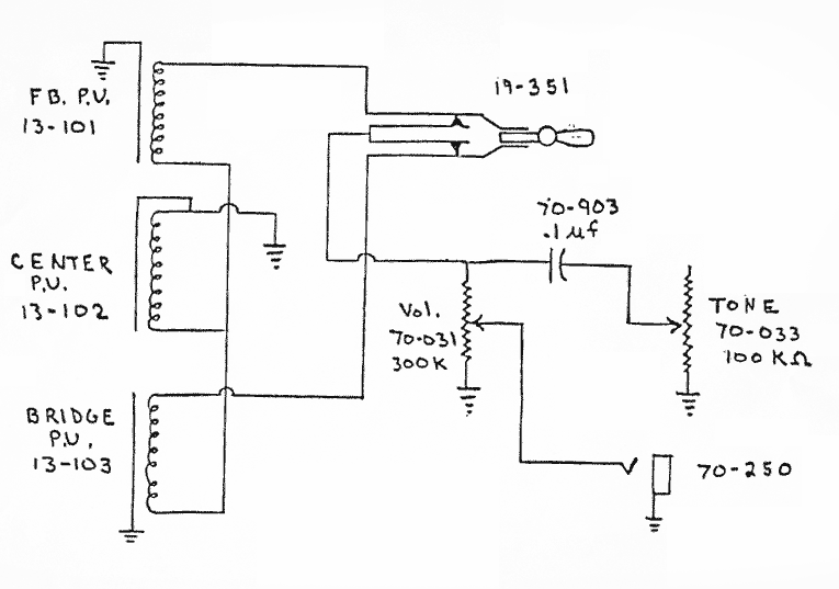
                      You hit the nail on the head that time. I think part of the trouble for me with all of this is that everywhere I go on line to look into guitar wiring and in 3 books I've gotten my hands on on the topic (and as you might imagine with the effort I've put in here, I've done a lot of looking), everything is done pictorially rather than by using real schematics. That's part of what I meant in one of these many messages when I said something to the effect that I find it very frustrating in a book or article that is supposed to enlighten you on guitar wiring when they give you a picture and tell you to attach wire A to terminal B, as if you were assembling a child's toy for Christmas, rather than to instruct you on appropriate schematic symbols and how to read and use them. I have been creating these pictures because I don't know, for lack of being able to find them anywhere, the standard symbols to be used in schematics.

                      I look at the schematic you have offered, and of course once I see it, a good deal of it is obvious. The pickups are labeled as such, they have coils, there are 3 of them here ( ;D ), and they have a wire going off to ground. I have no idea what it means that the ground on the middle pickup is depicted differently than on the other two and that the middle pickup appears to have another wire hanging off into space off to its left. I recognize the capacitor by its position and by the units labeled, but the symbol is not familiar. The pots are obvious (but seeing the grounds laid out in this way makes me recognize that I didn't stop to think earlier of the fact that the signal through the volume pot also goes to ground and how that might have influenced the current's travel--I guess that's a good part of the argument that schematics are better). I must presume 70-250 is the jack, by its position and because I don't see one anywhere else! In the same manner, I guess that 19-351 must be the pickup selector switch, but I haven't got a clue what sort of switch it is, and I am confused because I only see 2 of the 3 pickups connected to it. I have suspicion that some pickup connections to these switches are done through ground, but I don't see a ground symbol tied to the switch. I guess I'm just repeating the obvious--you can't make reliable use of symbols you don't know.

                      That being recognized and stated, can anyone recommend a good book on guitar wiring (or a book on general electronics that will cover components necessary to the guitar that might not commonly be used elsewhere, like pickups and pickup selector switches) that actually gets into the science behind it and goes as far as to instruct one on the use of standard schematic wiring symbols, rather than using pictures (some of which are frankly awful)? I don't need to be an electronics engineer, but I would benefit from a good general understanding of this stuff. I would love that!

                      Thanks, again Rob R

                      Comment


                      • #26
                        You know, I'm in a different position than those Electronics 101 students. I am retired prematurely due to a physical handicap (I am a family doctor), I've been playing the guitar for about 46 years, I am an avid woodworker, and I've got it in my head that I'd like to start making guitars as part of what I do to keep my head on straight during retirement. My youngest son shares this interest, so I hope it is something we can do together. That being said, you may understand that I am anxious to get more than a perfunctory understanding of this stuff, I have a brain and am used to using it, and I have the time to invest in study (not that I want to invest this much of it in this manner, this regularly, for too much longer , but I can't start wiring until the parts come in anyway!). I also have this annoying habit of being very obsessive about things.

                        Thanks, again Rob R

                        Comment


                        • #27
                          Originally posted by RobRed View Post
                          You know, I'm in a different position than those Electronics 101 students. I am retired prematurely due to a physical handicap (I am a family doctor), I've been playing the guitar for about 46 years, I am an avid woodworker, and I've got it in my head that I'd like to start making guitars as part of what I do to keep my head on straight during retirement. My youngest son shares this interest, so I hope it is something we can do together. That being said, you may understand that I am anxious to get more than a perfunctory understanding of this stuff, I have a brain and am used to using it, and I have the time to invest in study (not that I want to invest this much of it in this manner, this regularly, for too much longer , but I can't start wiring until the parts come in anyway!). I also have this annoying habit of being very obsessive about things.

                          Thanks, again Rob R
                          Rob:
                          Hang in there.
                          Check this out.
                          I looked at a couple of the lessons, looked great.
                          Volume I - DC : All About Circuits
                          When your not beating on guitar circuits, maybe you could go through some of this stuff.
                          Get your meter out. There's nothing like hands on to learn electronics.
                          T
                          "If Hitler invaded Hell, I would make at least a favourable reference of the Devil in the House of Commons." Winston Churchill
                          Terry

                          Comment


                          • #28
                            Terry:

                            Thanks a heap! I checked it out. It looks great. It's in my favorites. I'm getting tired for today, but I'll probably dive in tomorrow! I will get a lot of what I want to know about electronics, but unfortunately when I did a search through the site on "guitar pickups" it sent me off-site, so it does not have the guitar-specific info that I'd also like to have, but this will be a great start to getting a general understanding of the electronics that allow electric guitars to work.

                            Rob R

                            Comment


                            • #29
                              Originally posted by RobRed View Post
                              Terry:

                              Thanks a heap! I checked it out. It looks great. It's in my favorites. I'm getting tired for today, but I'll probably dive in tomorrow! I will get a lot of what I want to know about electronics, but unfortunately when I did a search through the site on "guitar pickups" it sent me off-site, so it does not have the guitar-specific info that I'd also like to have, but this will be a great start to getting a general understanding of the electronics that allow electric guitars to work.

                              Rob R
                              Pickups are Transducers. A big Inductor.
                              So you can look up inductors, and draw that symbol for the pickup.
                              Like was mentioned before draw the guitar layout like a Skematic, and it will make more since.
                              The pots are varible Resistors the pickups are inductor transducers, and you have Capacitors and switches.
                              Later,
                              Terry
                              "If Hitler invaded Hell, I would make at least a favourable reference of the Devil in the House of Commons." Winston Churchill
                              Terry

                              Comment


                              • #30
                                Good to know. I've made note of "transducers, inductors". Now I'm excited.

                                Rob R

                                Comment

                                Working...
                                X