Ad Widget

Collapse

Announcement

Collapse
No announcement yet.

Reality Check: DC Offset from Passive Pickup is Impossible?

Collapse
X
 
  • Filter
  • Time
  • Show
Clear All
new posts

  • Reality Check: DC Offset from Passive Pickup is Impossible?

    I'm pretty shaky on my electronics theory and wanted to check in on this.

    I am drawing up a simple buffer for a Jazz bass using a dual opamp - one side for each pickup. I was looking at building blocks for a starting point and thought maybe I could omit an input cap, because it seems there is going to be no DC offset from a simple coil, right?
  • #2
    Originally posted by Kindly Killer View Post
    I'm pretty shaky on my electronics theory and wanted to check in on this.

    I am drawing up a simple buffer for a Jazz bass using a dual opamp - one side for each pickup. I was looking at building blocks for a starting point and thought maybe I could omit an input cap, because it seems there is going to be no DC offset from a simple coil, right?
    That is right. So if you are using a bipolar supply where the "middle" is ground, you do not need the input capacitor.

    Comment


    • #3
      Originally posted by Mike Sulzer View Post
      That is right. So if you are using a bipolar supply where the "middle" is ground, you do not need the input capacitor.
      Even if he's not using a bipolar supply, he wont need an in put cap...simply bias the opamp +ve input pin via the pickup coil itself (effectively use it as a 7.5K resistor bias resistor!) ...ie rather than ground your coil - attach that end to your 1/2 VCC supply source..

      Comment


      • #4
        Which opamp (make and model) are you using? How big a voltage offset are you seeing, in volts?

        Many opamp types source large bias currents from their inputs, and there will be a voltage drop as this bias current flows through the DC resistance of the coil.

        Comment


        • #5
          Sorry I should have updated - I went ahead and used an input cap anyway. Opamp is TL072 and I just used the voltage divider biased style buffer because it seemed like the lowest parts count LOL. At unity gain I couldn't tell any difference in sound bypassing with a looper: identical source > identical sound. So ultimately I went with "good enough".

          Comment


          • #6
            Originally posted by Joe Gwinn View Post
            Which opamp (make and model) are you using? How big a voltage offset are you seeing, in volts?

            Many opamp types source large bias currents from their inputs, and there will be a voltage drop as this bias current flows through the DC resistance of the coil.
            So how do you explain the large resistances (typically 1M+) normally used for biasing up an oamp input pin ....the dc resistance of a pickups (sinlge coil or dual) pales into insignificance by comparison.

            Comment


            • #7
              Originally posted by peskywinnets View Post
              Even if he's not using a bipolar supply, he wont need an in put cap...simply bias the opamp +ve input pin via the pickup coil itself (effectively use it as a 7.5K resistor bias resistor!) ...ie rather than ground your coil - attach that end to your 1/2 VCC supply source..
              But you will need to bypass your 1/2 VCC source with a cap if you want it to be a good ac ground. It is better to have your pickup go to a real ground and use a cap at the input.

              Comment


              • #8
                Originally posted by Kindly Killer View Post
                Sorry I should have updated - I went ahead and used an input cap anyway. Opamp is TL072 and I just used the voltage divider biased style buffer because it seemed like the lowest parts count LOL. At unity gain I couldn't tell any difference in sound bypassing with a looper: identical source > identical sound. So ultimately I went with "good enough".
                With the voltage divider input, one must include the DC resistance of the coil in the divider equation to get the right answer. Unless you have an input capacitor.

                What is your circuit? A published circuit diagram would help us all to understand.

                Comment


                • #9
                  Originally posted by Joe Gwinn View Post
                  With the voltage divider input, one must include the DC resistance of the coil in the divider equation to get the right answer. Unless you have an input capacitor.

                  What is your circuit? A published circuit diagram would help us all to understand.
                  You would not use the coil resistance as part of the bias circuit since that would waste battery power when you could be using much larger resistors, and also you would not want to make the circuit dependent upon one particular coil resistance.

                  Comment


                  • #10
                    you can readily use a coil's DC resistance to bias up an opamp ....the lower side of the coil goes to a low impedance 1/2 VCC voltage the other side of the coil goes to the opamp +ve input pin - there's not much extra DC current flowing to speak of (unless you count microamps as being significant!) , so not much extra battery power being wasted.

                    I've done it many times in various test circuits - it works just fine.

                    Comment


                    • #11
                      Originally posted by peskywinnets View Post
                      you can readily use a coil's DC resistance to bias up an opamp ....the lower side of the coil goes to a low impedance 1/2 VCC voltage the other side of the coil goes to the opamp +ve input pin - there's not much extra DC current flowing to speak of (unless you count microamps as being significant!) , so not much extra battery power being wasted.

                      I've done it many times in various test circuits - it works just fine.
                      Yes, you can use the dc conductivity of the coil as a bias path. But you are not using its resistance to determine the bias in the case you mention. You are just using it as a low resistance path where the value of the resistance does not matter. Your 1/2 VCC source does not have to be particularly low in resistance; you can bypass it with a cap for low ac impedance. FET input op amps require tiny bias currents.

                      Comment


                      • #12
                        Originally posted by Mike Sulzer View Post
                        You would not use the coil resistance as part of the bias circuit since that would waste battery power when you could be using much larger resistors, and also you would not want to make the circuit dependent upon one particular coil resistance.
                        The point wast that the original poster's circuit might be doing just this, not that it was a good approach. We need to see the actual circuit diagram to tell what's going on.

                        Comment


                        • #13
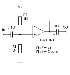
                          This x2 (two sides of TL072):


                          From Basic Buffers

                          Like I said I ended up keeping the caps. I breadboarded this exact buffer type as a starting point and A/B'd it with the bypassed signal and it sounded identical. I didn't do any scoping or anything, which I know would be more up to the standards of this community, but I am just a musician and I needed this for work. Once I get to Sunday I have a little time to tinker more if this is a bad setup. I built it on the kind of generic PCB that is laid out like a breadboard, so it is easy to make changes.

                          Comment


                          • #14
                            Seeing the circuit, if the 0.1 uF input capacitor is shorted, the DC resistance of the pickup (assume about 10 Kohms) will be in parallel with R1, changing the voltage divider ratio from 1/2 V+ to about 1/10 V+. This is a big change. If V+ is 10 volt, the output of IC1 will change from 5 volts to 1 volt when the input capacitor is shorted

                            Comment


                            • #15
                              Originally posted by Joe Gwinn View Post
                              Seeing the circuit, if the 0.1 uF input capacitor is shorted, the DC resistance of the pickup (assume about 10 Kohms) will be in parallel with R1, changing the voltage divider ratio from 1/2 V+ to about 1/10 V+. This is a big change. If V+ is 10 volt, the output of IC1 will change from 5 volts to 1 volt when the input capacitor is shorted
                              I think you mean 1/100 V+; so there will be about 100 mv on the input and the amp will not function since it needs to keep the common mode voltage about 3 volts above the negative rail (it can equal the positive rail.)

                              I suspect that there was more to this than just shorting out the capacitor.

                              Comment

                              Working...
                              X