Announcement

Collapse
No announcement yet.

Circuits involve active electronics and a dummy coil.

Collapse
X
 
  • Filter
  • Time
  • Show
Clear All
new posts

  • NateS
    replied
    Yes - it has a 3 way blade switch. The guitar is a schizophrenic combination of Luddite and High tech. It contains a Graphtech Ghost piezo saddle / 13 pin MIDI out, with P90's in a humbucker box, and minimalist controls. 3 way blade, and two volume knobs (three actually, magnetic and MIDI volume are stacked on the "volume" knob, the second "tone" knob is the summed Piezo volume, and contains a pull switch wired to the 'Dark' switch on the Acoustiphonic preamp. Magnetic & Piezo are always in 'blend' mode and manipulated by the volumes. If you're interested, you can find more over at the unofficialwarmoth forums. There's some finished pictures and a very long tortuous build thread.

    Minor edit: bypassed the bias divider, added DC path to ground on the high impeadance side of the pickups.


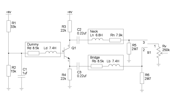
    Will the 2.7M to ground create a significant noise source? Since it's a 3 - way, maybe just putting it across the switch pins is enough to tame any pops, let the volume ground take care of things.

    Leave a comment:


  • CRU JONES
    replied
    That makes sense.

    Does it have a middle position?

    Leave a comment:


  • NateS
    replied
    I considered putting in balance but decided against it for a couple reasons. First off, the dummy coil is going to be another GFS Mean 90 that I rip apart and put just the coil in the space between the neck and bridge pickups. So it will be exactly matched with the bridge pickup, and nearly exactly matched with the neck. (Which btw, the RW/RP both pickups on position cancels very well.) Second, this guitar is a top routed strat, with a pickguard and 24 fret overhang (it's a Warmoth 24.75" scale conversion neck, so the overhang is about the same as a 22 fret neck). You can tweak for hum balance with the pickguard out, but once it goes together, I do not want it drifting. The neck's already been off and back on more than I'd like getting electronics tweaked (it has a Graphtech Hexpander/Acoustiphonic also.)

    I considered (and drew up) an alternate where the neck and bridge pickups were DC coupled to the phase inverter (and thus have a DC path to ground always) - and to their individual emitter followers. But the Graphtech already buffers the magnetic output, and there is no tone control in the guitar, so the only benefit that has is in the location of the buffer.

    Leave a comment:


  • CRU JONES
    replied
    Nate,

    I like it! Try it!

    The impedance of your transistor circuit will be minute compared to your pickups impedance.

    You might also consider a means to "balance" the Hum generated by the dummy with the Hum generated by the pickups.

    Maybe experiment with capacitively bypassing the Bias network. Technically, an LR is formed by R1||R2 +Rd... Possibly completely inconsequential.

    Nice work, good luck!
    Ethan

    Leave a comment:


  • NateS
    replied
    I'm considering this for a two pickup RW/RP guitar, which necessitates invertering the coil for one of the pickups. My question is - I understand that the follower described above adequately buffers the dummy, but what about the inverting leg of a single transitor phase inverter? It's much higher impeadance, right?

    Consider this:


    The boxes are pickups, I slapped in values from a similar pickup. And what about leaving the big honking inductor that is a pickup flapping in the breeze when it's not in circuit? In a passive guitar circuit, they do no harm, but here you've got the end of an inductor that's AC coupled on one end into a circuit thats still functioning.

    Leave a comment:


  • Steve A.
    replied
    Originally posted by David Schwab View Post
    Because now you were just hearing the dummy coil.
    In "normal" environments (i.e. at home) it seemed to work great. And it was only in the middle range of the pot that the noise came back; once you passed the midpoint the hum went away again. But that was definitely the wrong way to hook it up- I should have inserted between the pickup grounds and the guitar ground but I was doing series/parallel switching so that would have gotten complicated...

    I need to get back into dummy coils for some of my steel guitars. Like the 10 string Alkire E Harp that I just got...

    Click image for larger version

Name:	Alkire E Harp in case.jpg
Views:	1
Size:	51.2 KB
ID:	823975


    Steve Ahola

    Leave a comment:


  • David Schwab
    replied
    Originally posted by Steve A. View Post
    FWIW when using passive dummy coils in strats it was easiest for me to wire them up in series between the "tail" of the volume pot and ground. I thought that worked great until I was playing in one of those Bars from Hell which would be a real nightmare with single coil pickups. As I recall the dummy coil worked fine at full volume but as you turned the control down the hum would come back.
    Because now you were just hearing the dummy coil.

    Leave a comment:


  • Steve A.
    replied
    Digging up an old thread to add some irrelevant comments...

    FWIW when using passive dummy coils in strats it was easiest for me to wire them up in series between the "tail" of the volume pot and ground. I thought that worked great until I was playing in one of those Bars from Hell which would be a real nightmare with single coil pickups. As I recall the dummy coil worked fine at full volume but as you turned the control down the hum would come back. (I haven't done much with dummy coils since then- I never got around to trying a Suhr-style circuit which uses two pots although I did wire up a low impedance coil with 32GA magnet wire.)

    Steve Ahola

    P.S. The Gibson Blueshawk has a very interesting circuit using two P-90's and a passive dummy coil. The two pickups are RWRP with respect to each other and the selector switch inverts the leads from the dummy coil so that there is hum-cancellation in all positions (no need for the dummy coil in the middle position).

    Leave a comment:


  • Alan0354
    replied
    Originally posted by Mike Sulzer View Post
    Yes, the coils have to be very much the same. In the circuit with the FET you need a bit more sensitivity on the dummy, and so you can never be perfect at the high frequencies. In my case, if you turned the gain up very high you could hear a sort of wispy sound, the effect of the highest harmonics not canceling. You have a bit more flexibility with the op amps, but maybe more amp noise as well.

    Are you sure all your noise is magnetic and not some from electric fields, which do not cancel?
    Yes I am very sure because I have shield cavity. It really not depend of the shielding.

    You can find opamp that is very low noise. I use MC33178 or MC33179 that work with +/-2V, only draw about 1.6 or so mA supply. I yet to find a lower or equal voltage noise spec that draw less, in $1.50 range each and 3MHz BW. 4558 draw more than twice the current.

    Good thing about opamp is I drive direct and the impedance is very low, that's the reason I use a 3MHz opamp so the output impedance is theoretically zero ohm at 20KHz. And I can adjust the gain of the dummy signal without effecting the impedance.

    Leave a comment:


  • Mike Sulzer
    replied
    Originally posted by Alan0354 View Post
    I tried infinity also. No matter how you play with the loading, you can't get rid of the hum. As I said, getting rid of the 60 and 120 is easy, by the buzz is a different story. Yes you hear it lower, but not cancelling. Nothing like the true humbucking pup. You have to have very very similar coil for the dummy to get a better effect.
    Yes, the coils have to be very much the same. In the circuit with the FET you need a bit more sensitivity on the dummy, and so you can never be perfect at the high frequencies. In my case, if you turned the gain up very high you could hear a sort of wispy sound, the effect of the highest harmonics not canceling. You have a bit more flexibility with the op amps, but maybe more amp noise as well.

    Are you sure all your noise is magnetic and not some from electric fields, which do not cancel?

    Leave a comment:


  • Alan0354
    replied
    Originally posted by Mike Sulzer View Post
    The correct load on the dummy is infinity. See post 13 above. The idea is to think of the equivalent circuit of the dummy when it is in series with the pickup, and then make a circuit that puts the same voltage in series with the pickup, but with a low impedance. I do not think that it is perfect as you approach the self-resonance of the coils (maybe 15 KHz), but it should be pretty good even at that high a frequency.
    I tried infinity also. No matter how you play with the loading, you can't get rid of the hum. As I said, getting rid of the 60 and 120 is easy, by the buzz is a different story. Yes you hear it lower, but not cancelling. Nothing like the true humbucking pup. You have to have very very similar coil for the dummy to get a better effect.

    Leave a comment:


  • Mike Sulzer
    replied
    Originally posted by Alan0354 View Post
    In my design, I use op-amp, I invert the signal for the middle pup so even when you are in position 2 and 4 when both circuit are combined, the effect cancel out.

    What do you mean by adjusting the load on the dummy coil to get the frequency response? I did put a 250K volume pot as a variable resistor across the dummy coil and adjust the load and I cannot get rid of the noise at all!!! I tried using a lag lead network ( a cap or different value in series with the 250K pot) and cannot get rid of all the noise. Mainly the buzzing where you see like a spike and a few rings of about 10KHz riding on the 120Hz at the same point. Getting rid of the 60 and 120 is very easy, the buzzing is the kicker. The Suhr don't work very well in the demo either.
    The correct load on the dummy is infinity. See post 13 above. The idea is to think of the equivalent circuit of the dummy when it is in series with the pickup, and then make a circuit that puts the same voltage in series with the pickup, but with a low impedance. I do not think that it is perfect as you approach the self-resonance of the coils (maybe 15 KHz), but it should be pretty good even at that high a frequency.

    Leave a comment:


  • Alan0354
    replied
    Originally posted by Mike Sulzer View Post
    I did not know about the Ernie Ball design/patent. From the patent it is clear that he has an unnecessary complication in the design, adjustable loading on the dummy to get the frequency response right. From the explanation above, it should be clear that infinite load is correct and no adjustment is necessary as long as the dummy is very much like the pickup.
    In my design, I use op-amp, I invert the signal for the middle pup so even when you are in position 2 and 4 when both circuit are combined, the effect cancel out.

    What do you mean by adjusting the load on the dummy coil to get the frequency response? I did put a 250K volume pot as a variable resistor across the dummy coil and adjust the load and I cannot get rid of the noise at all!!! I tried using a lag lead network ( a cap or different value in series with the 250K pot) and cannot get rid of all the noise. Mainly the buzzing where you see like a spike and a few rings of about 10KHz riding on the 120Hz at the same point. Getting rid of the 60 and 120 is very easy, the buzzing is the kicker. The Suhr don't work very well in the demo either.

    Leave a comment:


  • Mike Sulzer
    replied
    Originally posted by Kindly Killer View Post
    I did. I don't remember the exact number, but it was reasonable...
    OK, good. If you connect the dummy coil directly to the amp and listen for the hum, and then connect it to the circuit, jumpering across the pickup, do you get a similar level of him, but maybe more higher frequency buzzing?

    Leave a comment:


  • Kindly Killer
    replied
    I did. I don't remember the exact number, but it was reasonable...

    Leave a comment:

Working...
X