-
Today i bought some copper wire, 6 mm**2 (between AWG 9 and 10). Now it is time to order the CTs and to decide which size magnets would be best (among many other things...) -
I buy my electronics at RS Components International , the only downside is that they only deliver to companies.
But at my work we have to order regularly, so I order my stuff along.
We have an order coming up, so if you want I can order some for you, pm me if you would like that.Leave a comment:
-
Dear Hans,
Although i can buy them through mercateo i would prefer to know a direct source.Originally posted by MisterBzr View Post
BTW: https://www.magnet-shop.net/ seems to have more sizes in stock than the supermagnete storeLeave a comment:
-
Thanks a lot.
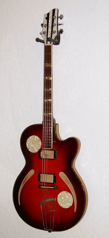
My idea was to use magnets of about the thickness of the wire, say diameter 6 mm and thickness 2-3 mm, glued into the loop. Or use double magnets per string, similar to the jazzbass pickups. It looks as if i might be fine with these. Yes, the construction should be as lightweight and grazile as possible because i do want to keep the openings as soundholes. Btw: this is the target - a German thinline archtop from the 60s:
Leave a comment:
-
Beate,Originally posted by bea View Post
I don't know why, but I completly missed the recent activity of this thread, so I'm a bit late to the party.
In Europe you can easily obtain a talema as-104 CT, and if not then I'll happily send you a few.
All my pickups have strong neodym magnets (I obtained them from supermagnete.de or you could check aliexpress.com) and this works fine.
As for string distance, I think it is pretty much the same as with a conventional pickup.
I think that with some experimenting you could make a fitting solution for your archtop guitar.
HansLeave a comment:
-
Bea,Originally posted by bea View Post
To estimate/calculate the output impedance without test equipment, you can use some simple calculations. Use this wire calculator Resistivity Calc to obtain the total resistance of the low impedance string loop usually measured in micro-ohms. If you use a 500 turn current transformer (CT) then you must multiply the resistance of the string loop by the secondary turns squared or 250,000.
Let's assume that we are using AWG 13 0.0720" diameter and 166.7 micro-ohms per inch for an 8 inch string loop then the total string loop is (166.7 X 8) is 1,333.6 micro-ohms. The current transformer output is near 1,333.6 microohms times 250,000 equals 333.4 ohms. If you use two strands of wire AWG 13 then the results will be about one half. Also, if you use a current transformer(CT) with a higher turns ratio then you must mulitply the string loop resistance by a larger number. A 750 turn CT is now 562,500 times 166.7 microohms or an output of 750.15 ohms or a little too high for a typical mic mixer. Here is when the current transformer can become a filter and change the sound of the string loop, current based pickup.
When using Neodym magnets try keeping then as far away from the strings as the height or thickness of the magnet. K&J Magnetics has some nice Neodym magnets 2" long by .25" wide by .125" thick. You can use what ever magnets you have on hand just make sure the magnets are secure to the string loop. The closeness to the string is based on how much string mass is ferrous metal, string tension, and thickness of the magnet(s).
If you use two CTs, one on each end of the string loop, you can play with getting two different sounds out of this design. Attach only one CT to the audio amp with the other CT open, then short out the second CT and you will hear the volume go up a little and the tonal emphasis will change a little also. This is because when the string loop goes through the second CT the total impedance of the string loop goes up and as the impedance goes up the amount of current induced goes down, thus reducing the output voltage also. The sound difference is also what it sounds like to use a thicker string loop as shorting out the second CT makes the string loop sound like you are now using a thicker wire in the string loop.
You should play with a few of the Talema AX series current transformers 500, 750 and 1000 turns is as high as I would go. You will need to fill the center 5mm center opening with as much wire as you can turn into a multi-strand string loop to keep the impedance in a useful mic range. If you use the 1500 turn CT you will be up near the line input range with an output impedance near 3000 ohms for a single strand of AWG13.
I hope this gets you going in the right direction. This is fun stuff to play with. Remember this design has a relatively low noise as there is a less exposed large bundle of fine wire to act as an antenna. There is only one loop of very thick wire that is connected to the XLR mic ground or pin 1. Pins 2 and 3 attach to the output wires of the current transformer. As you load down the output impedance of the current transformer, you will start cutting off the high frequencies first. This design pickup will have a very low Q and provide a pretty flat response as long as the AX series toroid output impedance is kept near or below 300 ohms by using sufficiently thick string loop wire for the higher turns ratio CTs (750, 1000, 1500 turns).
Joseph RogowskiLeave a comment:
-
Back to the original topic - a few questions summing all this up for a beginner.
If i use a current transformer similar to the Talema Ax-500 (or Ax-1500...) i need a closed loop of wire, don't i? These seem to be easier to obtain for me. I might use 2.5 mm (AWG13-14) wire for the first experiments, simply because i have it available an feel able to solder it.
If i use neodym magnets these will be pretty close to the strings. How strong (large) may or should such magnets be in order not to affect string vibration noticeably?
Target guitar is a 5 string with empty humbucker mounting rings. The loop might be a narrow "bridge" across the hole reaching from one mounting point to the other, and the CT will be mounted on the bass side. Or should i wire two CTs in parallel?Leave a comment:
-
Cigar box guitar.Originally posted by bbsailor View Post
No i haven't. It'll actually take some months because of a few other ongoing projects with higher priority. And the the usual surprises of our lives... But we have the discussion now and i am therefore learning now; i intend to keep this thread in mind for future reference.Have you obtained any CSE187L current transformers yet?
Indeed. But if i leave the pickup hole open for acoustic reasons i can not use a pickup in its place. Therefore i had the idea if a single loop pickup in shape of a pickup mounting ring might be used.The acoustic sound of your archtop with the pickups removed is an acoustic issue and not related to what a pickup sees.
That was also my idea. Unfortunately this seemed to be correct - i hoped i had overlooked something.This current transformer low impedance pickup will respond to string distance from the coil the same way that a traditional high Z pickup will respond with different distance settings.
PS: at present i am doing an SG bass with LoZ pickups in humbucker covers. I feel that the single loop approach will not help me much in this project because i want to retain the aperture of a traditional pickup - in this case i am going to try something like "LoZ Darkstars". Remember when we were discussing Darkstars - i dis ask many questions, among them many strange ones, now i will implement.
(The project is documented here: http://www.gitarrebassbau.de/viewtop...p=76508#p76508)Last edited by bea; 10-16-2014, 11:33 PM.Leave a comment:
-
The problem with using very thick wire is that the upper guitar harmonics are very weak beyond the resonant point and this resonant point in high Z pickups defines the steep cutoff point in the pickup response. However in these low Z pickups the resonance is much higher but the skin effect may contribute to higher harmonics not generating enough current to capture those subtle upper harmonics that provide a more acoustic sound. The alternative to this is to use many strands of AWG 20 bundled like Litz wire as you observed in your previous post. The key is to clean the ends of each strand and use thin wall copper tubing to secure and solder the bundle ends of the string loop going through the SPCT-251 CT primary space.Originally posted by charrich56 View Post
Here is an experiment to do with two CSE187L CTs. Face the two CT together with the primaries aligned. Use thin wall copper tubing to join these two CT together forming a tiny one string loop in which you can put a single short .25" diameter magnet. When I used my Extech LCR meter here are the measurements I obtained.
Measurements of the output on CT 1 with the CT 2 OPEN: Divide the measured impedance by 250,000 (for a 500 turn CT) to get the equivalent string loop impedance.
120Hz: 443.6 mH; 164.5 ohms; Q 2.082; equals a total string loop of 658 micro ohms
1KHz :161.05 mH; 864.5 ohms; Q 1.172; equals a total string loop of 3458 micro ohms
With CT2 SHORTED, here are the new measurements from CT 1:
120Hz: 47.36mH; 142 ohms; Q 0.2577; equals a total string loop of 568 micro ohms
1KHz: 16.89mH; 149.6 ohms; Q .7109; equals a total string loop of 598.4 micro ohms.
What you will hear if you now place a magnet in the center of this 2 CT setup and hold near a guitar string with CT1 attached to an XLR mic input is that the level and tone will change when you short out CT2 versus leving it open. This is the equivalent of using different gauge wire on the primary string loop. You can also put a 1K ohm pot (used as a variable resistor load) across the CT2 and have a variable tonal adjustment. The important take away from this experiment is that the total string loop resistance, including any installed CT transformer primary wire gauge, the transformer core lamination permeability, primary to secondary coupling (including leakage inductance) will determine the tonal center of this type of pickup.
This is a synthesis of several years of playing with this stuff.
Joseph RogowskiLeave a comment:
-
Joseph,
Thanks again for all the time and effort you are spending on this thread. Actually, with the experiment you did with the SPCT-251 and AWG 6 wire, 880 ohms would be just fine for a low-noise JFET front end preamp and about 25-30 dB gain, assuming we could get about 10-20 mV RMS out of the thing. That is in the sweet spot for the onboard preamps I am building for really low noise and OK battery draw.
What I am suggesting is that the 150-300 ohm output impedance range although ideal for an external standard low-Z mic input, doesn't necessarily have to be a constraint for an onboard preamp. In fact we want more voltage output to lessen the gain needed since we are bridging the preamp input.
So it might be a valid experimental direction to go more than 1 turn or even the use the parallel multiple conductors or PC board approach, even if the output Z seen through the CT isn't in that ideal range.
-CharlieLeave a comment:
-
Charlie,Originally posted by charrich56 View Post
Using stacked PC boards does not provide a low enough DCR path to to make an effective string loop typically measured in microohms. See the attached web link for a handy resistance calaculator. Resistivity Calc
The default metal is copper but any other metal can be selected for your calculation. A string loop is typically about 5 to 6 inches to span a typical 2 inch string width. Make sure you use the inches option rather than feet to see your answer in microohms. I doubt that circuit boards would be an efficient use of space but give it a try. The concept of thinking in microohms to have the string loop generate a high enough induced current from a vibrating string, requires a shift in thinking from making traditional voltage based high Z pickups.
To keep the output impedance of the current transformer(CT) in the 150 to 300 ohm range requires the use of pretty thick wire. That is why using current transformers with very thin (like AWG 16 or 17 primary turn wire) makes pickups with too high of an output impedance. The fix for this situation would be to add a supplemental primary loop(s) over the CT secondary winding wired in parallel with the installed primary. If you use a 500 turn CT the output impedance would be calculated by multiplying the turns ratio squared by the total string loop resistance including the CT primary being in series with the external string loop wire which would typically be between AWG 12 and AWG 6 to generate enough current to be converted by the transformer action.
A CSE187L with the primary installed AWG12 winding bent into a shorted primary and soldered has an output impedance of between 78 and 80 ohms as measured by an Extech LCR meter on the CT secondary. This value includes the leakage inductance of about 17 ohms which tends to look like an impedance in series with the primary. There is no secondary or supplemental loop used with this measurement. If I add one additional loop of AWG 18 wire, the measured output impedance drops to about 70 ohms. If I use 5 inches of AWG 11 wire, the DCR of this wire is 105 microohms per inch for a total of 525 microohms. The added impedance of .000525 ohms times 250,000 adds 131.25 ohms to the primary impedance for a total output impedance of about 211 ohms. As you can see, thicker primary string loop wire will lower the output impedance. That is why making good, low resistance connections between the string loop and the CT is very important with these designs. Stacking many circuit boards together has too many places where less than optimal connections can occur. If you use a CT with a turns ratio of 1 to 1000 the output impedance would be 4 times higher and you would need to use very, very, very thick wire or copper to keep the output impedance in a low-Z microphone range.
In one of my experiments I used a Prem Magnetics SPCT-251 CT that has a 1 to 2000 turns ratio, This means that the DCR of the primary loop is now multiplied by 4,000,000 to calculate the output impedance. This SPCT-251 has no prewired primary but a square .160" opening where the user loops the current carrying conductor. I obtained some square AWG 6 wire that just fits in the .160" opening. I bent 2" of this wire into a U shape, drilled a hole through the two ends to make a shorted loop with a piece of AWG 12 wire, soldered it and measured the output impedance of this shorted primary loop at about 880 ohms, much too high for a low Z mic input but OK for a 10K ohm line input.
I hope this information gets you and all the interested forum members thinking about guitar pickups in a new way that opens opportunities to be innovative. Check out another thread I started: "Moving coil pickups for the technically curious" where I use the voltage generated on the metal string similar to what is done in a ribbon microphone but with the guitar string being the ribbon.
I hope this helps?
Joseph RogowskiLeave a comment:
-
Originally posted by bbsailor View Post
Joseph,
CBG= cigar box guitar. There is a lively community of people who enjoy making and playing these. The ones I've seen have been 3 string instruments.
Thanks for the very detailed information. I don't have a specific archtop construction in mind but would like to experiment with a flattop acoustic without a traditional single large sound hole.
Talking about parallel conductors for the string loop: Do you know of anyone who has experimented with stacked PC boards for the string loop? The image would be of a Fishman Fluence type coil but with only about 4-8 stacked PC boards with double sided layers. With thick copper boards, maybe with silver plating, and multiple redundant plate-through holes and relatively large inter-board connector wires, it might be possible to get the overall loop resistance pretty low with parallel conductors - and this would allow some geometric design freedom in placing the conductors on the boards, tailoring width, etc. Kind of a "flat spread-out Litz" sort of thing. You could also selectively introduce some amount of eddy currents back into the design, using Bill Lawrence's idea of eddies as "seasoning" to the pickup sauce.
Holes in the stacked PC board assembly would be just dandy places to put the magnets, too.
Fishman may have the stacked PC board pickup ring-fenced by patent though... but maybe wouldn't apply to a single loop design.
-CharlieLeave a comment:
-
Originally posted by bbsailor View Post
Joseph,
CBG= cigar box guitar. There is a lively community of people who enjoy making and playing these. The ones I've seen have been 3 string instruments.
Thanks for the very detailed information. I don't have a specific archtop construction in mind but would like to experiment with a flattop acoustic without a traditional single large sound hole.
Talking about parallel conductors for the string loop: Do you know of anyone who has experimented with stacked PC boards for the string loop? The image would be of a Fishman Fluence type coil but with only about 4-8 stacked PC boards with double sided layers. With thick copper boards, maybe with silver plating, and multiple redundant plate-through holes and relatively large inter-board connector wires, it might be possible to get the overall loop resistance pretty low with parallel conductors - and this would allow some geometric design freedom in placing the conductors on the boards, tailoring width, etc. Kind of a "flat Litz" sort of thing. You could also selectively introduce some amount of eddy currents back into the design, using Bill Lawrence's idea of eddies as "seasoning" to the pickup sauce.
Fishman may have the stacked PC board pickup ring-fenced by patent though... but maybe wouldn't apply to a single loop design.
-CharlieLeave a comment:
-
[/QUOTE] or two or more loops in parallel (in contrast to serial like in a coil), correct?
What about the distance from the strings?
The application i asked was for a CGB where the PU should be mounted under the top. No soundhole or whatever.
The other application - mine, mentioned earlier during this thread: imagine an archtop with holes for standard humbuckers, similar to, say, an ES-175. Imagine that the acoustic sound is better with these holes open. Imagine a loop in shape of a humbucker mounting frame, and hence pretty far away from the strings. Will it be possible to get a sufficient singal from such a setting?[/QUOTE]
Bea,
Yes, adding two or more primary string loops in parallel is the same as using heavier wire. Go to a wire table to see the effect of using multiple parallel wires to calculate the effect on the current transformer output impedance based on my previous posts.
What does CGB mean?
Have you obtained any CSE187L current transformers yet?
The acoustic sound of your archtop with the pickups removed is an acoustic issue and not related to what a pickup sees. This current transformer low impedance pickup will respond to string distance from the coil the same way that a traditional high Z pickup will respond with different distance settings. The real issue is signal to noise ratio, as lower noise can support higher amplifier or mixer gain and farther pickup distances to the string generator source. You need to experiment with CSE187L (or similar) current transformer pickups to hear what sounds good to you. Let us know what you find.
Joseph RogowskiLast edited by bbsailor; 10-16-2014, 02:35 AM.Leave a comment:
Leave a comment: