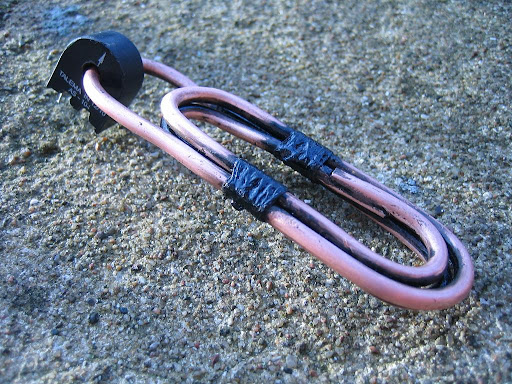
I've made a current transformer pickup with three primary windings, not really knowing what to expect. I had a good piece of 3.5 mm copper wire that was just long enough for three windings, so I decided to try and see how it would sound. The sound is decent, but not very exiting. I'm about to try different magnets at different distances to the strings, so I might be able to improve the sound. (Image omitted.)
I've made a ct pickup with three primary windings, not really knowing what to expect. I had a good piece of 3.5 mm copper wire that was just long enough for three windings, so I decided to try and see how it would sound. The sound is decent, but not very exiting. I'm about to try different magnets at different distances to the strings, so I might be able to improve the sound.
I hope having more primary windings does something positive to the impedance. But I haven't found out what three primary windings instead of one does to the impedance of the signal that comes out of the current transformer. Will it have three times the impedance of the signal from a pickup with only one primary winding. Or nine (3 square) times that high. Or something completely different?
So the question is: what is the relation between the number of primary windings and the impedance of the final transformed signal?
If anyone can point to useful formulas or information - or inform me - I'd be happy.
/Alex
Alex,
Try one sting loop and a CT at each end of the loop. Then, try listening to the CTs in series and parallel and then again into a mic matching transformer. You should hear some interesting tonal variations doing this experiment.
It is good to see some daring people try this CT pickup stuff.
I've made a ct pickup with three primary windings, not really knowing what to expect. I had a good piece of 3.5 mm copper wire that was just long enough for three windings, so I decided to try and see how it would sound. The sound is decent, but not very exiting. I'm about to try different magnets at different distances to the strings, so I might be able to improve the sound.
I hope having more primary windings does something positive to the impedance. But I haven't found out what three primary windings instead of one does to the impedance of the signal that comes out of the current transformer. Will it have three times the impedance of the signal from a pickup with only one primary winding. Or nine (3 square) times that high. Or something completely different?
So the question is: what is the relation between the number of primary windings and the impedance of the final transformed signal?
If anyone can point to useful formulas or information - or inform me - I'd be happy.
Very encouraging! I figured that I'd try to create some wood covers to insert into the routed humbucker slots in the body (so that the gold, chrome or black chrome ball mags would look like they are in the body itself), and have specially drilled and routed holes to keep the mags in place. As soon as I can get the setup completed, I'll post more info and pics.
Yes, you can try neo-type magnetic balls, however orienting them properly and finding a way to secure them may present you with a challenge. The general advantage of this design is low noise, wide bandwidth (without the classic resonant hump the defines an electric guitar sound) and ease of fabrication. The ease of fabrication is what using neo-type magnetic balls challenges.
Give it a try and post your results so we can all learn something from your effort!
Is it possible to use magnetic balls rather than strip or bar magnets in this design? I think that it would have a cool look and wonder if neodym balls would hinder the idea or be worth a try?
Why so much microphonics?
I'd tend to say the whole circuit is mechanically too rigid, plus aluminum alloy makes a high pitched sound when struck, and the mini transformer is secured tightly on one end only leaving it free to vibrate in the field if ever the pickup is struck etc
Or perhaps the transformer is insufficiently shielded, from outside intererences and from the PU's magnets?
*are the transformer plates grounded by contacting the aluminum frame or are they grounded via wiring?
Should the transformer be mechanically secured in some king of potting and not contact rigidly the frame (having the inside gap filled with soft resin or wax between frame & plates for example?)
*besides redirecting the flux more efficiently under the bar magnets with a ferromagnetic plate as bbsailor proposed, would there be an additional solution to prevent the magnets from inducing current directly in the transformer bobbins?
Which solutions for shielding the circuit?
A member stated that there is a copper plate under the magnets: copper is a poorman's choice, it isn't made to block really magnetic fields that well. Unless it isn't copper, on the gutshot photos, it seems to be an alloy more silvery in color than copper....?? (I don't own the pickup so I cannot see for myself)
LEt's say the aluminum frame was pure aluminum, uncoated, untreated : when the surface corrodes and eventually pits, would that impact the overall quality? The alumitones are apparently anodized, so they're oxidized in a controlled manner, controlled thickness as well.
Any influence at all on frequency response with degraded & oxidized low-z loop material surface? ( imagine a pure copper low z frame so corroded you could see the copper acetate layer on it, for example?)
All,
Thanks for the information and encouragement.
I figure the coils I have are at maybe 500 turns, but I was wondering what I could do for a core I could put around a continuous loop. I have some permalloy that I could cut in long strips and wind through a couple of the coils set up in a humbucking configuration similar to the picture of the Alumitone layout. The coils are a bit shorter and fatter than the Lace design, but I would hope that won't make much difference.
But with what Helmuth shares about microphonics with the Alumitone he tested, I'd like to know if that represents other people's experience with the Alumitone and Transensor designs. I was mostly excited at the prospect of less noise pickup, not trading noise for microphonics.
Would winding a continuous length of permalloy ribbon through a couple of small coil form bobbins quasi-toroid style around the single turn loop post work for the low signal level involved?
I've got some nice tiny-wire coils wound on transistor-radio-sized bobbins. I was thinking I could pull the stacked cores out of the bobbins and use the coils to play with the Alumitone single-turn design idea. I was thinking that putting the transformer outside the frame instead of underneath the frame would get me a really flat pickup with just the loop under the strings at the neck. Might be useful for a custom design.
Mr. Coffee,
Give it a try. What you want to do is put a low resistance (under 1 milliohm) loop under the string with a magnet in the center. Then you need to couple that low resistance loop to the current transformer secondary which will be your transistor radio sized bobbins. The number of trurns on those bobbins will determine the truns ratio and the voltage/impedance of the output. The coupling of the permallow bobbin to the low resistance loop will determine the efficiency of the transformer.
Feeding a guitar amp, you will need an output in the 100mv to 200mv range but if you feed a mic input you only need about 5mv to 10mv output. Grounding is very important to minimize hum. Ground the low resistance loop. Ground the strings.
Try ordering a few small CSE187L current transformers and play with using these. They have a 1 to 500 turns ratio. They work very well into an XLR mic input or into a microphone matching transformer with a 1 to 10 turns ratio boost. Putting a piece of thin ferrous metal under the magnet and under the low resistance loop will redirect the underside of the magnetic field and result in about a 25% to 30% increase in output.
Post a photo of what you come up with. Who would have thought that inexpensive current transformers could produce a guitar pickup? Share what you learn from your own experiments and we all learn something.
Would winding a continuous length of permalloy ribbon through a couple of small coil form bobbins quasi-toroid style around the single turn loop post work for the low signal level involved?
I've got some nice tiny-wire coils wound on transistor-radio-sized bobbins. I was thinking I could pull the stacked cores out of the bobbins and use the coils to play with the Alumitone single-turn design idea. I was thinking that putting the transformer outside the frame instead of underneath the frame would get me a really flat pickup with just the loop under the strings at the neck. Might be useful for a custom design.
Bringing to mind a question...Why bother? Yeah, I know, cable capacitance and all that, but... Just put in a Stratoblaster and get some real gain happening! Worked for Lowell George...
Interesting. It is pretty much the response you might expect, sort of within the range of a typical humbucker, but without the dip below the resonance due to the eddy current loss. I wonder which aspects if this were intentional and which are just the way it worked out.
I remember when the pickup first came out they had a flatter response and people didn't seem to like them as much, so they must have decided to wind the transformer hotter.
Also this design was around a while in the form of the Lace Transsensors which used a copper loop instead of the aluminum frame. So they had time to tweak these and see what people like best. Not surprisingly they voice them similar to hi-z pickups.
Last edited by David Schwab; 08-22-2010, 11:29 PM.
Reason: typos
Interesting. It is pretty much the response you might expect, sort of within the range of a typical humbucker, but without the dip below the resonance due to the eddy current loss. I wonder which aspects if this were intentional and which are just the way it worked out.
Here are the frequency responses of a Lace Alumitone (humbucker size),
measured with the Pickup Analyzer from 40 Hz to 10 kHz.
1. With 470 pF capacitive load and five different resistive loads: 10 M (nearly
open circuit), 1 M (no pot, tube amp input), 333 k (one 500 k pot and 1 M tube
amp input), 200 k (two 500 k or one 250 k pot and tube amp input), 111 k (two
250 k pots and tube amp input). The capacitors on the tone controls are
nearly a short circuit in the kHz range and can be neglected.
Small ripples on the curves are caused by interference from the environment
and have nothing to do with the pickup.
For experiment, I removed the two plastic magnets and the copper foil on the
rear side. The resonance peak got about 0.5 dB higher with 10 M load then,
otherwise there is no fundamental difference.
The roll-off on the bass side is due to a RL-highpass built of the serial
resistance of the winding and the input inductance of the transformer.
The transformer consists of two coils so that a humbucking effect is
accomplished. If you use one coil only (white wire as hot output) the
secondary inductance is halfed and the resonance peak appears at a higher
frequency. It is sensitive to hum then.
Leave a comment: