 Tweet
Tweet
This is my first post, so please bear with me.
I play an upright bass that has a dual piezo pickup. *It came with a preamp that sounded so bad I literally threw it away. *What I want to build is an Ampeg b15n based dual channel preamp that I can use to plug into house sound, my regular bass amp, or use to record direct. *
My bass has a stereo jack on it, so the preamp will have a single stereo input. *It will have separate volume, treble, and bass controls for each channel, and I will use push/pull tone pots for the bass and treble boost.
I want to make the preamp circuits as close as possible to the original B15n but obviously setup for a piezo. *Also, when playing at louder volumes, or when the acoustics of a room are terrible, my bass feedsback at about 100hz. *So I want to do a notch filter on each channel that drops 100hz, but leaves everything above about 120hz and below 80hz. I will have a separate notch for each channel that is switched with a small micro switch.
Here is a link to the pickup I am using:
Bass Master RB - K&K Sound
Here are some questions I have:
1. *Input Resistor � the pickups input resistance is 1m per channel. *Should I match that, or should I got with something like a 4.7m input resistor like a lot of the peizo preamps I see online.
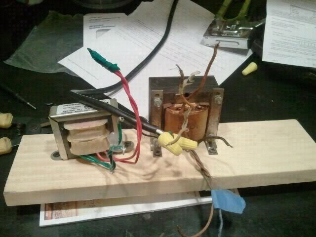
2. *Rectifier � I want to use a tube rectifier, but I am not sure if the tranny I am using will let me, or what rectifier tube to use. Here is a pic of the small trans that I will be using (tranny on the left):
3. *Notch Filter � No idea how to do this. *Any ideas?
4. *Is there anything else I need to do to the basic b15n preamp circuit to better work with a peizo?
5. *I want to make sure I have loads of clean headroom, so anything that will help that...
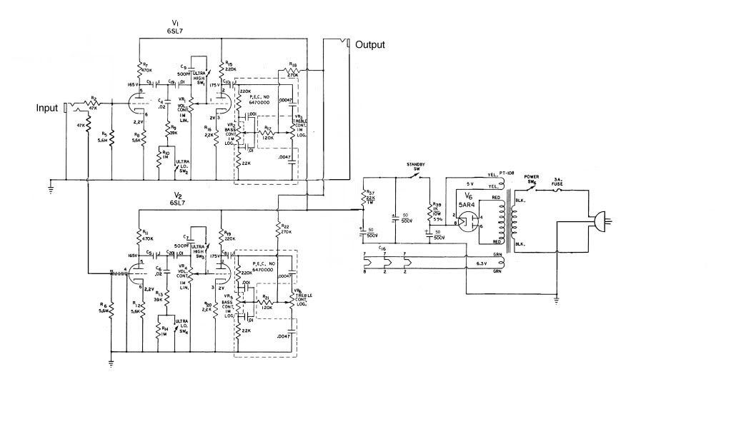
Here is a schematic I did to start with. *I still need to make sure the input impedance is correct for a piezo. *And I need to figure out where to put the notch filter(s) and exactly how to do them.
Thanks for any input!
I play an upright bass that has a dual piezo pickup. *It came with a preamp that sounded so bad I literally threw it away. *What I want to build is an Ampeg b15n based dual channel preamp that I can use to plug into house sound, my regular bass amp, or use to record direct. *
My bass has a stereo jack on it, so the preamp will have a single stereo input. *It will have separate volume, treble, and bass controls for each channel, and I will use push/pull tone pots for the bass and treble boost.
I want to make the preamp circuits as close as possible to the original B15n but obviously setup for a piezo. *Also, when playing at louder volumes, or when the acoustics of a room are terrible, my bass feedsback at about 100hz. *So I want to do a notch filter on each channel that drops 100hz, but leaves everything above about 120hz and below 80hz. I will have a separate notch for each channel that is switched with a small micro switch.
Here is a link to the pickup I am using:
Bass Master RB - K&K Sound
Here are some questions I have:
1. *Input Resistor � the pickups input resistance is 1m per channel. *Should I match that, or should I got with something like a 4.7m input resistor like a lot of the peizo preamps I see online.
2. *Rectifier � I want to use a tube rectifier, but I am not sure if the tranny I am using will let me, or what rectifier tube to use. Here is a pic of the small trans that I will be using (tranny on the left):
3. *Notch Filter � No idea how to do this. *Any ideas?
4. *Is there anything else I need to do to the basic b15n preamp circuit to better work with a peizo?
5. *I want to make sure I have loads of clean headroom, so anything that will help that...
Here is a schematic I did to start with. *I still need to make sure the input impedance is correct for a piezo. *And I need to figure out where to put the notch filter(s) and exactly how to do them.
Thanks for any input!
Comment