Announcement

Collapse
No announcement yet.

DALLAS/SHAFTESBURY - 1961-62 combo

Collapse
X
 
  • Filter
  • Time
  • Show
Clear All
new posts

  • DALLAS/SHAFTESBURY - 1961-62 combo

    Hi!

    Iīm restoring this baby:
    [ATTACH]3686[/ATTACH]
    [ATTACH]3687[/ATTACH]
    [ATTACH]3688[/ATTACH]

    I had no schematic, so using a Selmer one, who is similar, i draw this one (just power amp):
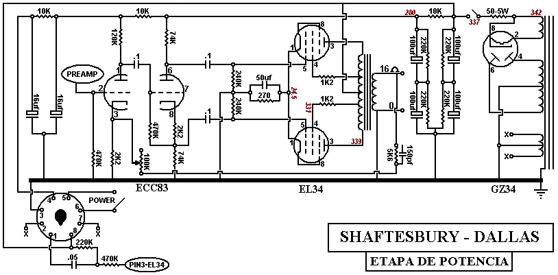


    The problem is the 100+100 uf filter cap.
    Isnīt to much for a GZ34 rectifier?

    The cap in my amp is nor original (is a new TAD).
    Maybe, the pre-owner, change the value.

    What do you think?

    Any other conment about the schematic will be welcome.
    Last edited by tboy; 12-03-2008, 08:20 PM.

  • #2
    cool little amp.

    re: the large 100uF, (assuming that is how it's wired) it looks to me that the series R would help make a bigger than usual cap value work ok (like a choke input). (I guess the R increases impedance of the GZ34 and limits peak current so it doesn't damage the cathode or something like that.) In terms of cost a resistor would be cheaper so the cost factor would favor the R over a choke esp. since it would need to be rated to handle the whole current draw of the B+ line it looks to me.

    Comment


    • #3
      Thanks!

      I have a pic from another amp like mine.
      I,m using it to restore to factory specs.

      [ATTACH]3690[/ATTACH]

      there are some diferent values and adds in the rectifier area, but most seems to be the same.
      Last edited by tboy; 12-03-2008, 08:22 PM.

      Comment


      • #4
        Very nice little amp. You said that you have used the selmer schematic. Are you using the selmer with it's own values or you have substituted them from your amp?
        Could you map out the preamp section? I had a Dallas Rangemaster Combo and it didn't have the original preamp circuit in it. I am trying to track down a schematic for it but it's almost impossible. So every bit of help is appreciated, because this amp's power section is very close to the rangemaster's. The tremolo in particulair was strange in deed. Does this one have a tremolo?

        Comment


        • #5
          Iīm usinf the Selmer schamatic just a base for the real one.
          I donīt gonna change any values, except maybe, in the Power supply rail and EL34īs cathode bias resistor. Voltage are really high and need a tweek.

          Iīm still working in the preamp schematic. As soon i finish the schematic, iīll post it here. Maybe,it take me weeks, because this is just a free-time hoby.

          Ahh! My amp has Tremolo as yours, but it dont work (still....)

          stay on tune!!

          Comment


          • #6
            Originally posted by chocopower View Post
            Iīm usinf the Selmer schamatic just a base for the real one.
            I donīt gonna change any values, except maybe, in the Power supply rail and EL34īs cathode bias resistor. Voltage are really high and need a tweek.

            Iīm still working in the preamp schematic. As soon i finish the schematic, iīll post it here. Maybe,it take me weeks, because this is just a free-time hoby.

            Ahh! My amp has Tremolo as yours, but it dont work (still....)

            stay on tune!!
            That's excellent. The best new I've heard for ages. The tremolo circuit on my amp is strange, but I think I mapped it out as best I could, because I have some photos someone kindly sent to me. At the moment it is in a test build situation. If it works, I'll post the schematic and the photos. Your amp must be the closest thing to the Dallas Rangemaster Combo I had. I am trying to build another one, but this time I would like to get it as close to the original as possible. The tremolo was very close to the AC10 or AC15 Vox circuit, so I used that. However this time I would like to get the original to work.

            Comment


            • #7
              Hi again!

              Here is a new version for the power section.

              [ATTACH]3689[/ATTACH]

              Mods:

              The first 100-100uf cap cut to 50-50uf.
              A variable NFB lood added.
              Last edited by tboy; 12-03-2008, 08:15 PM.

              Comment


              • #8
                That's really nice work. Looking at the photo of the underside of the amp I could actually follow your schematic. However I am more interested in the preamp section. Any chance before Christmas? Hand drawing is fine if it is too difficult to translate into a printed circuit like the power section.
                Keep working on it.
                Last edited by tboy; 12-03-2008, 08:16 PM.

                Comment


                • #9
                  I see you are on tune...


                  Preamp draw is in working process.

                  I draw the 1rst gain stage for the two channels (EF86) and need to chek some values in the tonestack.
                  The tremolo secction remaind untouched....
                  As said, tremolo is nor working in my amp, and previous owner make some strange mods.

                  Maybe next year....

                  Comment


                  • #10
                    Ahh!!

                    Could you make some pics from power secction unit?

                    Comment


                    • #11
                      Pictures for power section?

                      What do you mean Chocopower?

                      Comment


                      • #12
                        Chocopower,

                        the two caps stacked in series are half the value 100 - 100=50. the resistors are there to balance the voltages between the caps. Generally speaking 50mfd isn't too much for a GZ34.

                        Marc

                        Comment


                        • #13
                          Originally posted by cservonyec View Post
                          What do you mean Chocopower?
                          Sorry for my bad english....

                          I need some photos from your amp.

                          Comment


                          • #14
                            Originally posted by Marc View Post
                            Chocopower,

                            the two caps stacked in series are half the value 100 - 100=50. the resistors are there to balance the voltages between the caps. Generally speaking 50mfd isn't too much for a GZ34.

                            Marc
                            Sorry. I delete original schematic.. The amp cames to me with a 100 uf cap for the two first filter stages.
                            I add two 100uf in series to cut down the capacitance to 50 uf.
                            As you say, 50 uf is cool for a GZ34, but the 100 uf was too much....

                            Preamp schematic semi-finished. Next week, maybe...

                            Comment


                            • #15
                              Pictures from my Dallas Amp

                              Preamp schematic semi-finished. Next week, maybe...

                              I have a few pictures from various sections of the preamp.
                              Attached Files
                              Last edited by tboy; 04-16-2010, 12:28 AM. Reason: removed extraneous quote tag

                              Comment

                              Working...
                              X