 Tweet
Tweet
I'm still a bit new at this, so questions keep arising as I try to get my first amp built so here it goes...
The following pictures says that the wires coming from the pilot light need to go to "all x filaments." I see that the tubes have x filaments labeled on the 7 and 9 pins, but how should I connect them; just run a continuous wire through each of those joints then ground off? I'm really not sure about this so if any body could shed some more light it would be greatly appreciated.
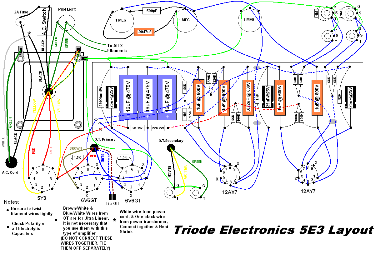
The following pictures says that the wires coming from the pilot light need to go to "all x filaments." I see that the tubes have x filaments labeled on the 7 and 9 pins, but how should I connect them; just run a continuous wire through each of those joints then ground off? I'm really not sure about this so if any body could shed some more light it would be greatly appreciated.
Comment