Announcement

Collapse
No announcement yet.

Anode resistors switching

Collapse
X
 
  • Filter
  • Time
  • Show
Clear All
new posts

  • Anode resistors switching

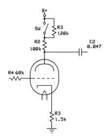
    Hi everybody! I'd like to ask if it's ok to add a switch for selecting another plate resistor for a preamp tube while the amp is running. I mean something like that:


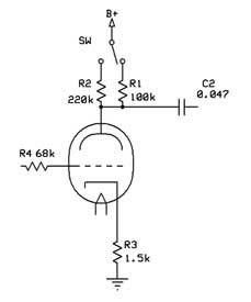
    Is it going to introduce any pops or other noises when switching?
    Thanks in advance!

  • #2
    The high voltage there is an issue, you would need a suitably-rated switch. The HT would also tend to introduce arcing, which might cause a pop - though not too much of any noise created that side of the anode resistor will make it through into the signal chain. A 240v mains-type toggle switch might be the answer.

    Comment


    • #3
      ...the "safer" method is to always leave one resistor in the circuit (typically the highest R-value) and switch "on" parallel resistor(s) which, because it's in parallel with the highest R-value, yields a lower R-value.

      ...this approach NEVER allows the plate circuit to go "open" while switching between plate R-values.
      ...and the Devil said: "...yes, but it's a DRY heat!"

      Comment


      • #4
        Thank you very much for your help! I'm considering using resistors in series, and bypassing one of them with the switch (with the appropriate rating), to get the values I want, without "opening" the plate:


        Again, thanks a lot!

        Comment


        • #5
          this looks cool... can you post your sonic results?

          Comment


          • #6
            WHy not mount your 220k permanently, then switch a parallel 220k in and out?


            yes I realize that makes 110k, but if that difference bothers you, then make that parallel resistor 210k or whatever works out.
            Education is what you're left with after you have forgotten what you have learned.

            Comment


            • #7
              Since this is the Theory section, I'll give a little tip. Do you remember the parallel resistor equasion: 1/Rtotal=1/R1+1/R2 ? It works real well because 1/Rtotal-1/R1=1/R2. Use the (1/x) key on a calculator and get the value in seconds. 100K (1/x) - 220K (1/x) = (1/x)

              In this case 220K||183.333K=100K

              Switching will create a pop though. Keeping one resistor in the circuit all the time makes it less.
              WARNING! Musical Instrument amplifiers contain lethal voltages and can retain them even when unplugged. Refer service to qualified personnel.
              REMEMBER: Everybody knows that smokin' ain't allowed in school !

              Comment


              • #8
                And I guess, the higher the non-swithable R, the less the "popping", right?
                Thanks a lot guys! Lowell, I'll try to post the results as soon as i complete it.

                Comment


                • #9
                  Full/Bright/Fat switch

                  Due to the high voltage and concerns with "popping" ......

                  I personally would not add a switch for plate resistors. If you are simply trying to alter the gain factor ....... it is much easier and safer to use a cathode switch.

                  You can parallel caps and/or resistors for different gain values and the voltage is lower. I use a Full/Bright/Fat switch on most of my amps and sometimes will parallel both a resistor & cap on one side of the switch.

                  Look at the cathode switch on V1

                  With respect, Tubenit
                  Attached Files

                  Comment


                  • #10
                    You don't find you need bleeders (or pre-chargers) for those switched caps?

                    Comment


                    • #11
                      Originally posted by Tubenit View Post
                      Due to the high voltage and concerns with "popping" ......

                      I personally would not add a switch for plate resistors. If you are simply trying to alter the gain factor ....... it is much easier and safer to use a cathode switch.

                      You can parallel caps and/or resistors for different gain values and the voltage is lower. I use a Full/Bright/Fat switch on most of my amps and sometimes will parallel both a resistor & cap on one side of the switch.

                      Look at the cathode switch on V1

                      With respect, Tubenit
                      With equal respect, it really depends on what you want to do.

                      Changing the cathode bypass cap value will change the frequency at which the stage gain increases due to the bypass effect (above a certain frequency the gain will be increase by around 6 dB), but leave the low frequency and high frequency gain levels unchanged. Increasing the anode resistor from say 100K to 220K will have little effect on the frequency where the boost occurs, but it will increase gain at all frequencies- about 2 dB bypassed (high end), and about 4 dB unbypassed (low end). It will also alter the distortion characteristics, and the bias point will move in the direction of reduced headroom.

                      MPM

                      Comment


                      • #12
                        cathode switch

                        I have used a Full/Bright/Fat switch on maybe 10 different amps. All but one of them worked fine ( no popping) without the added resistors. And I did add a resistor on that one amp's switch but don't remember exactly how I did it?
                        I am thinking it may have been between the cap and ground?

                        If you parallel a resistor with cap you can change both bias and frequencies. See below. Because of the lower voltage on the cathode, I can use a mini-toggle for the switch safely.

                        I am not saying it is a better way to do it, but it's the method I personally use & may be another option to consider?

                        With respect,
                        Attached Files
                        Last edited by Tubenit; 03-01-2009, 05:29 PM.

                        Comment


                        • #13
                          Originally posted by martin manning View Post
                          It will also alter the distortion characteristics, and the bias point will move in the direction of reduced headroom.
                          MPM
                          That's exactly what I'm after, altering the distortion character. With small anode resistors, say 48k, the sound is warmer, bluesier, with even order harmonics. With larger values, the sound becomes "glassier", introducing odd order harmonics. Tubenit, I think I'll also use cathode resistor/capacitor switching. About the high voltage of the anode, I'm not concerned, since the "job" of switching will be done by relays.
                          Thanks everybody!!!

                          Comment


                          • #14
                            Originally posted by Tubenit View Post
                            Due to the high voltage and concerns with "popping" ......


                            Look at the cathode switch on V1

                            With respect, Tubenit
                            That cathode switch on V1 is different. It does not interrupt the DC path. Big difference. My my layouts, I never interrupt the DC path. As such, the parallel switch as shown above would be the more preferred way to do it.

                            -g
                            ______________________________________
                            Gary Moore
                            Moore Amplifiication
                            mooreamps@hotmail.com

                            Comment


                            • #15
                              Not wise as it will also alter the operating point of the valve

                              I suspect that you want to alter the gain

                              so do the gain min option with the cathode resistor unbypassed, and max option with the cathode resistor bypassed. get rid of swich thunp by putting a 33k resistor across the swich coz the bypass cap is always charged.

                              see the schematic attached to this post ->
                              post about cathode bypass capacitor
                              Last edited by Suusi M; 03-03-2009, 03:49 PM.

                              Comment

                              Working...
                              X