Announcement

Collapse
No announcement yet.

Traynor YBA-1 2-3 prong power cord question. . .

Collapse
X
 
  • Filter
  • Time
  • Show
Clear All
new posts

  • Traynor YBA-1 2-3 prong power cord question. . .

    I don't mean to be dense, but I was initially planning to simply replace the 2-prong cord in my new (to me) '73 YBA-1 w/ a 3 prong cord, run the green wire to the chassis & remove the 'death cap'. I wanted to be sure I was on the right track, so I did a little Google-ing and found this page:

    http://www.unclespot.com/2to3prongconversion.html

    According to that drawing, I should move the fuse to before the switch & on the 'black' wire. The white wire should just go straight to the transformers. This would require a bit more moving around than I was planning. I took before & 'during' pix to illustrate how my amp is wired. Would someone please take a peek & tell me if I'd be safe/fine just simply hooking the black & white wires back up to the same location they were at on the old wiring (white to top of 120V outlet, black to bottom)?
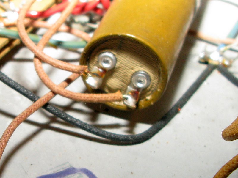
    Attached Files

  • #2
    I wouldn't recommend that anybody tell you that is "OK". There are liability issues here. Modern desing (and UL, etc.) rules dictate that, whenever possible, the fuse is the first thing after the power cord and comes before any parts that a person can come in contact with. That includes the power switch. Also, make sure that you wire the power cord to the inside (tip) of the fuse holder, not to the part that comes in contact with the fuse holder cap. Same reason, you don't want to electrocute yourself while changing a fuse.

    A lot of folks may just telly you that there amp has been wired the way you suggest for 1/2 million years and they never got shocked. It doesn't matter; it doesn't make it right.

    Sorry, man. Do the hard work. You'll feel better about it in the long run anyway knowing that it is 100% done right.

    Comment


    • #3
      Wonderful! Thanks for the explanation. I'm 100% into doing it the 'right' way, just need to know the how & why of it. . .

      SO, if I'm understanding correctly, the key is that the hot (black) wire goes FIRST to the side of the breaker (no fuse holder in this amp, only a push-button circuit breaker) that opens to protect the circuit (and anything that might've come into contact w/ it, for example, my fingers) THEN to the power switch, correct?

      What about the 2-prong outlet? I'd love to bypass it, but it has leads running up to the pilot lamp, etc. Move all of those over to the power switch? And the ground switch, should I leave that in the circuit? Before or after the switch? I know it won't have a function - maybe best to totally bypass the ground switch and outlet, 'eh? If I were to do that, the black wire would go to the circuit breaker, then the power switch and nothing else with the leads for the pilot lamp, etc. from the 120V outlet & ground switch moved to the power switch? And the white wire would just go straight to the power switch? Hmm. . .

      Comment


      • #4
        The 2 prong outlet is a nice place to solder wires to (especially the white one). Somebody please correct me if I am wrong but I don't think it is a problem to keep the 2 prong outlet wired up as long as it is polarized and you wire the hot/neutral to the correct tabs. There are plenty of things that are appropriate to run off of a 2 prong outlet (like wall warts and some switching power supplies for example).

        In that case the black wire would go to (in order): circuit breaker, switch, 2-prong outlet, then off of the outlet to both the transformer and pilot light hots.

        The white wire would go directly over to the 2-prong outlet then branch off to the transformer and pilot light.

        If wiring to the 2-prong outlet is not appropriate (or if you just want to leave it out) then just use some shrink tubing and solder the filament/transformer neutral connections directly to the white wire on the power cord.

        FYI, it is also goo practice to make sure that the green chassis ground wire is a bit longer than both the hot & neutral wires. That way, if the power cord is ripped from the chassis somehow the ground wire will be the last thing disconnected. The thought is that if the ground wire stays connected the hot can still have an opportunity to short to the chassis and possibly blow a breaker. Even worse, if the hot rested on the chassis and the ground was already ripped out you could get electrocuted.

        Comment


        • #5
          Thank you SO much. I really appreciate all the hand-holding. I'm usually a little more confident, but I want to do this just right & most of the diagrams & pix I can find are for Fenders, etc. Will be sure to post pix once I'm done so that this thread can help others. . .

          Comment


          • #6
            Alright, work is done (for tonight).

            I wired it as you suggested with one change: instead of the black wire going:

            circuit breaker, switch, 2-prong outlet, then off of the outlet to both the transformer and pilot light hots
            I went:

            circuit breaker, switch & left the original split to the transformer & lamp on middle lug of switch, added wire going to lower lug on 120VAC outlet.

            Hopefully there isn't some reason I'm missing to have the hot leads for the transformer & lamp moved to the outlet, the upper (white) lug on the outlet is already crowded & I only wanted to move/change runs of wire where necessary. I'd already left the ground wire a bit longer than the hot & neutral + I terminated it in a ring lug at one of the bolts that holds a transformer to the chassis. I'm glad to have retained the 2 prong outlet, it would be handy if I were having trouble finding an outlet for my 1SPOT adapter.

            Anyhow, pictures, as promised:

            1st, the finished (I think) 3 prong conversion:


            and a few gratuitous shots:


            Now, I need to get some new electrolytics!!!

            Comment


            • #7
              Fired it up this morning & everything seems good. . .

              Thanks again, bit time, for the help.

              Comment


              • #8
                Cool amp. Nice job, yes I'd change those filter caps.
                Stop by my web page!

                Comment


                • #9
                  Thanks!

                  Anyone have suggestions for what the closest thing would be to these old Mallorys? I'd love to keep them mounted in the same little hoop brackets, if at all possible.

                  Comment


                  • #10
                    Originally posted by drasp View Post
                    I went...circuit breaker, switch & left the original split to the transformer & lamp on middle lug of switch, added wire going to lower lug on 120VAC outlet.
                    Wired this way, the ac socket is now switched on and off with the power switch and is loaded to the circuit breaker. If you use the socket with something large, it may cause the circuit breaker to pop.

                    You might want to rewire it.

                    Comment


                    • #11
                      Good point. There should be nothing wrong with wiring the outlet before the breaker. On the other hand, if it is working for you leave it. A fused outlet isn't a bad thing either.

                      Comment


                      • #12
                        Yeah, beyond allowing me to leave more of the original wiring intact, I actually liked the idea of having a breaker on the 2-prong + control w/ the amps power switch. The only thing I'd ever run from it would be my 1SPOT (9VDC wart) to power a handful of pedals, but I usually have a power strip to run everything from. I can see no reason anyone should try to run anything that draws much at all from the back of a head. . . Everything is working great so far. I have practice w/ it on Tuesday - looking forward to it!!!

                        Comment


                        • #13
                          I'd forget about trying to match the physical size and go with 50uf/50uf/500vdc JJ caps.

                          Dave

                          Comment


                          • #14
                            Yeah, I'm not going to worry about the physical size. Just wanted to be sure that if there was a direct replacement for those Mallorys I knew about it.

                            I'm planning to go with Axial F&Ts so I can at least mount them in the same location. I've had folks recommend both 33uf & 47uf caps (originals were 40uf). What are the benefits/reasons for under/over rating the caps?

                            Comment


                            • #15
                              Originally posted by drasp View Post
                              What are the benefits/reasons for under/over rating the caps?
                              With the caps you are referring to, the values are so close that there would be no difference at all.

                              Too small a cap value can cause increased hum and ripple. Too large a value can stress the rectifiers, (this is more a tube rectifier problem).

                              In the olden days caps were often tolerance rated as +80% and -20%. So I'd go with the modern version of the 40 and use the 47uF caps.

                              Comment

                              Working...
                              X